9 sata 300-8elp board layout, Sata 300-8elp board layout – Avago Technologies MegaRAID SATA 300-4XLP User Manual
Page 42
3-12
SATA 300 Storage Adapter Specifications
Version 1.4
Copyright © 2004–2006 by LSI Logic Corporation. All rights reserved.
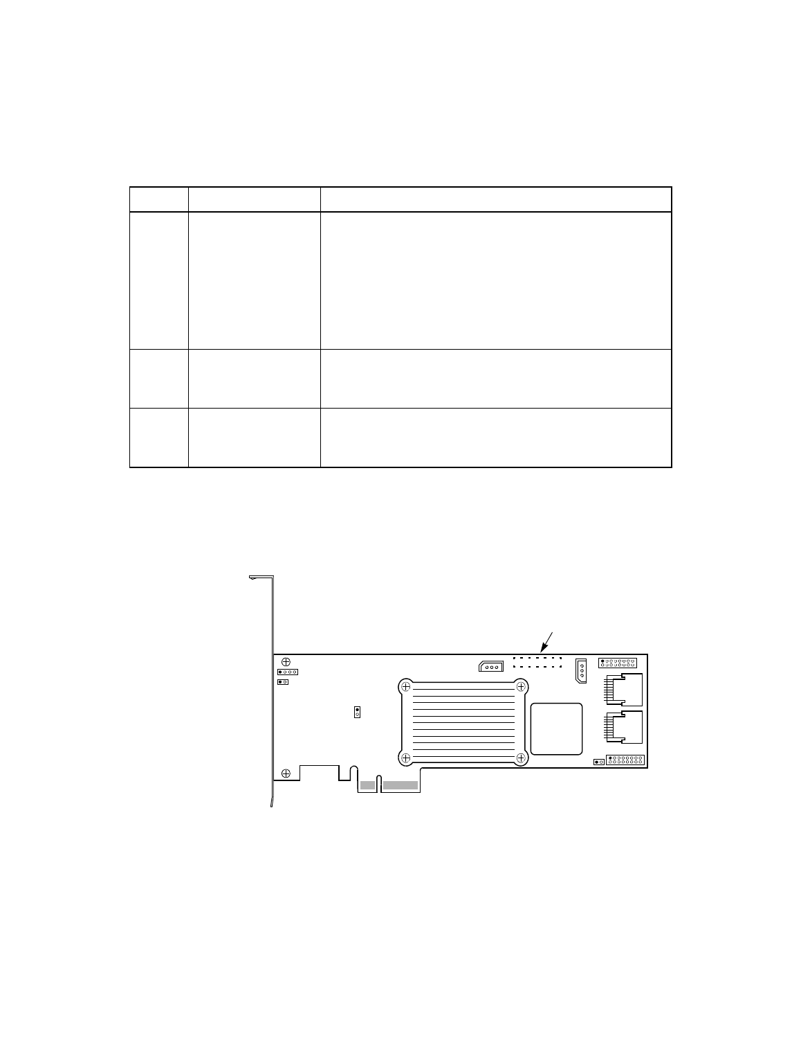
3.2.9
SATA 300-8ELP Board Layout
provides the layout of the SATA 300-8ELP board.
Figure 3.5
SATA 300-8ELP Board Layout
J7
BIOS Disable jumper
2-pin jumper.
The BIOS function is enabled or disabled in the software
depending on the status of this jumper.
No jumper: BIOS is enabled. This is the default.
Jumper: BIOS is disabled.
1. Note: The card does not function as a RAID controller if this
jumper is mounted.
J9
LED SATA Activity
Interface Connector
16-pin (8x2) jumper.
Provides LED interface individually to eight SATA ports. The LED
indicates SATA activity on specific ports.
J10
LED Drive Fault
Interface Connector
16-pin (8x2) jumper.
Provides LED interface individually to eight SATA ports. The LED
indicates a drive fault on specific ports.
Table 3.5
SATA 300-8XLP Connectors and Jumpers (Cont.)
Jumper Type
Description
J3
J9
Ports
J10
P1
U13
J8
J1
J4
J5
J6
J7
J2
U14
0–3
4–7
J11
Connector Located
on Back of Board
Ports