Avago Technologies LSI SAS 3041X-R User Manual
Lsi logic sas3041x-r host adapter, Quick installation guide
®
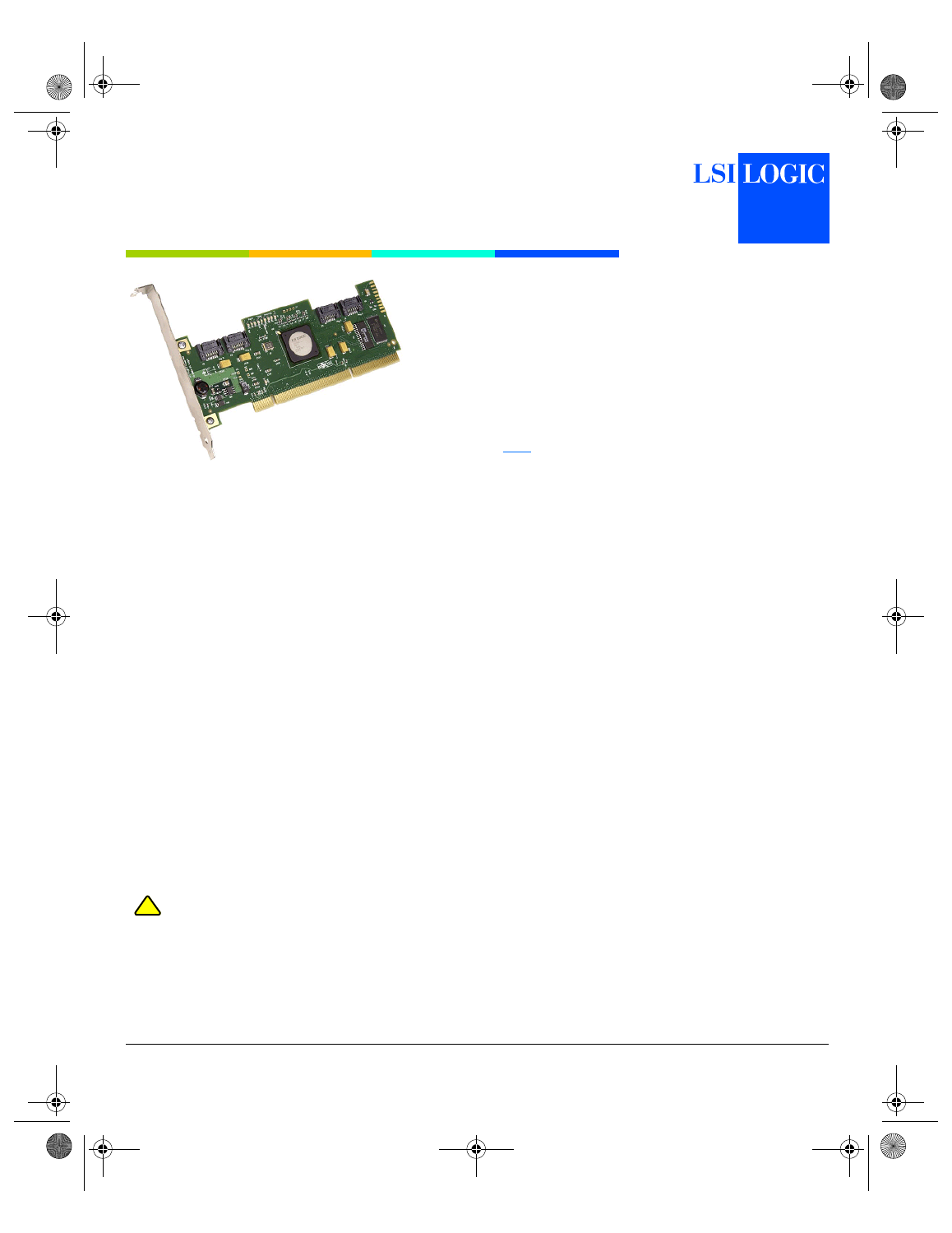
Thank you for purchasing the LSI Logic SAS3041X-R
Serial Attached SCSI (SAS) to PCI-X Host Bus Adapter
(HBA). Please take a few minutes to read this Quick
Installation Guide before you install the SAS3041X-R.
If you need more information about any topic covered in this
guide, refer to the other documents on the accompanying
LSI Logic Device Drivers & Utilities CD.
C O N T E N T S O F T H E L S I L O G I C D E V I C E
D R I V E R S & U T I L I T I E S C D
The LSI Logic HBA CD contains utility programs, device
drivers for various operating systems, and the following
LSI Logic documentation:
• LSISAS (Serial Attached SCSI) PCI/PCI-X Host Adapters
User’s Guide
• Fusion-MPT™ Device Management User’s Guide
• LSI Logic HBA technical product briefs
Q U I C K H B A I N S T A L L A T I O N
To install the SAS3041X-R, follow these steps:
Step 1
Unpack the HBA and inspect it for damage.
Unpack the HBA in a static-free environment.
Remove the HBA from the anti-static bag and
inspect it for damage. If it appears to be
damaged, or if any component is missing, contact
LSI Logic or your reseller support representative.
Step 2
Prepare the computer.
Turn off the computer and remove the power cord
from the back of the power supply. Remove the
cover from the chassis. Be certain to disconnect
the computer from the power supply and from any
networks before installing the controller card.
Step 3
Insert the SAS3041X-R in an available
PCI/PCI-X slot.
Locate an empty PCI/PCI-X slot. Remove the
blank bracket panel on the back of the computer
that is aligned with the PCI/PCI-X slot you have
selected. Save the bracket screw when present.
Align the HBA to a PCI/PCI-X slot. Press down
gently but firmly to properly seat the HBA in the
slot. The following figure illustrates how to insert
the HBA in a PCI/PCI-X slot.
Note:
The SAS3041X-R is keyed for a 3.3 V slot. The
keying of edge connector J1 prevents the card
from being installed in a 5 V slot.
Step 4
Secure the bracket to the system’s chassis.
Install the bracket screw, when present, or
engage the system retention mechanism to
secure the HBA to the system’s chassis.
Step 5
Connect the serial cable(s) between the HBA
and the serial hard disk drive(s) (HDD).
The SAS3041X-R has four internal SATA 7-pin
signal connectors, each connecting to a 3 Gbit/s
SAS port. Use an appropriate cable to connect the
SAS3041X-R to SAS/SATA storage devices. To
connect directly to SAS hard disk drives, it is
necessary to use a cable that has a SAS device
connector on one end (HDD side) and a standard
SATA 7-pin connector on the other end (HBA end).
This cable may also be used for direct connection
to SATA drives. For connection to internal SATA
hard disk drives, a standard internal SATA cable
may also be used (note that using a standard SATA
cable requires availability of a 15-POS power cable
from the main power supply). The preceding figure
illustrates the connector locations on the
SAS3041X-R HBA and the use of a standard SATA
cable for connection to a SATA hard disk drive.
When connecting the SAS3041X-R to a backplane,
there are two possible cable configurations. The
first configuration is use of a standard SATA cable
when the backplane uses standard SATA 7-pin
connectors to route the signals to the hard disk
drives. A second configuration is necessary when
the backplane uses a SAS internal wide port
connector (SFF8484). In this case, a
backplane-based fan-out cable is required. This
cable has an SAS wide port connector on one end
(backplane side) and four SAS 7-pin signal
connectors on the other end (HBA side).
Make a backup of your data before changing your
system configuration.
!
CAUTION
LSI Logic SAS3041X-R
Host Adapter
Quick Installation Guide
LSISAS3041X_R_qig.fm Page 1 Friday, October 14, 2005 4:52 PM