Avago Technologies ACPL-336J-000E User Manual
User's manual, Acpl-337j, Isolated igbt gate driver evaluation board
ACPL-337J
Isolated IGBT Gate Driver Evaluation board
User's Manual
Quick-Start
Visual inspection is needed to ensure that the evaluation board is received in good condition.
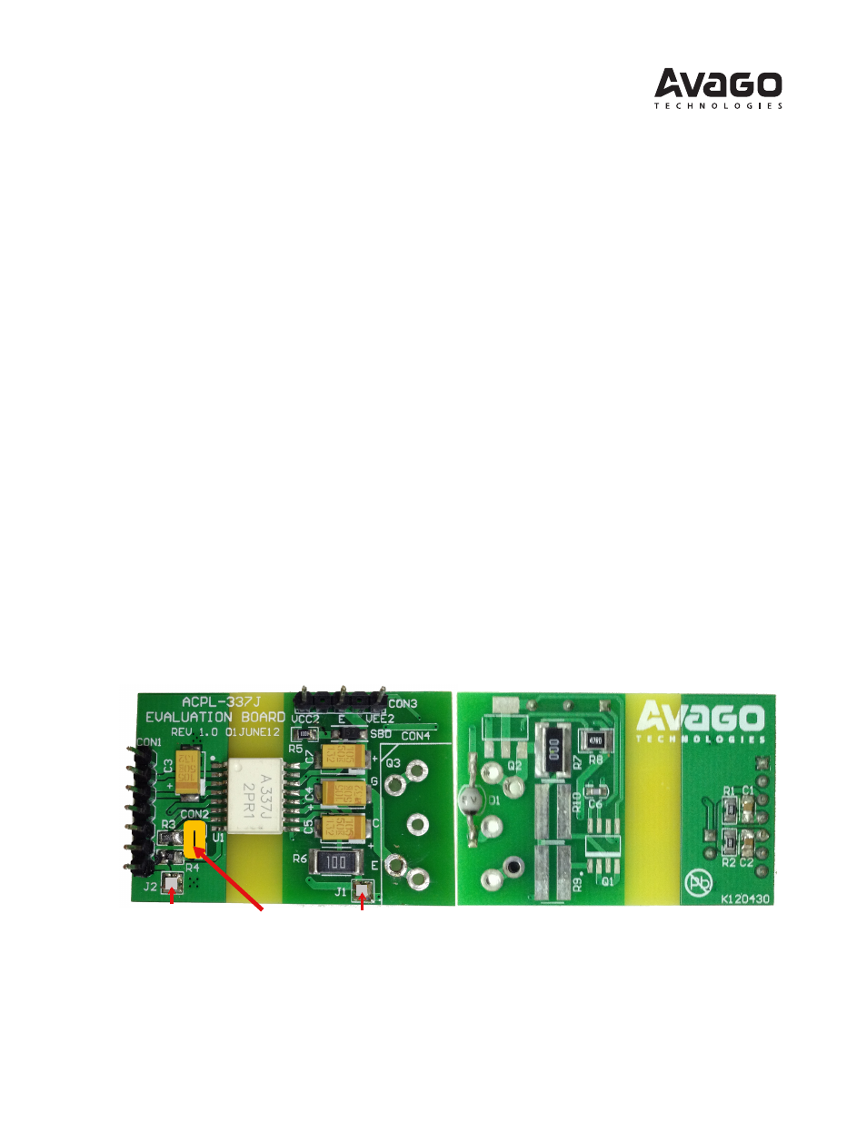
Default connections of the evaluation board are as shown (see Figure 1):
1. Q1 (Bipolar Buffer Driver), Q2 (Miller Clamp Bipolar) and Q3 (IGBT) are not mounted. An actual IGBT should be
mounted at Q3 (for TO-247 package), or connected to the driver board through short wire connections from the
holes provided at Q3.
2. CON3 is provided to allow for positive supply (V
CC2
) and negative supply (V
EE2
) with respect to V
E
(marked as E, which
is connected to emitter pin of the IGBT).
3. J1 jumper is shorted by default to connect the output to the Gate pin of the IGBT, through gate resistors R6 (10
Ω) &
R7 (0
Ω);
4. R9, R10 and Q1 (provisions for buffer driver) are not mounted by default. These components will be needed if more
than 4 A of gate drive current is required (J1 must be removed while R7 must then be shorted to accommodate this).
5. Similarly, Q2 is not mounted by default. This component should be mounted, however, if Miller Clamp current of
more than 2 A is required;
6. CON2 and J2 are shorted by default to allow for a single input PWM signal at Vin+ (pin 2 of CON1) to drive the LED of
ACPL-337J. If a separate LED drive signal (across R3 and R4) is required, then CON2 (and J2 if R4 cannot be grounded
to Gnd) must be opened.
7. CON1 is provided to allow for the power supply (+5V) to be connected across V
CC1
and Gnd, TTL signal drive at Vin+,
direct driving of LED, plus /UVLO and /Fault feedback.
Figure 1. Actual ACPL-337J evaluation board showing default connections
Once inspection is done, the evaluation board can be powered up in seven simple steps, as shown in Figure 2, in simula-
tion mode, without the need of actual IGBT.
J1 shorted
J2 shorted
Component Side
Solder Side
Gnd
Vin+
Vcc1
/UVLO
/Fault
LED
+
LED
−
CON2 shorted