Avago Technologies ASSR-1411-001E User Manual
Data sheet, Solid state relay, assr series, Evaluation board
Solid State Relay, ASSR Series
Evaluation Board
Data Sheet
Description
This evaluation board features Avago Technologies’
Solid State Relay (SSR) with MOSFET output, ASSR
Series, in 4 different IC package footprints. They are 8-
Pin DIP with Gull Wing Surface Mount, 6-Pin DIP with
Gull Wing Surface Mount, 4-Pin SO, and 4-Pin SSOP.
ASSR-xx2x Series, 2-form A (dual channel), is featured
in 8-Pin DIP with Gull Wing Surface Mount footprint
and offers 2 identical channels for evaluation. ASSR-
xx1x Series, 1-form A (single channel) Solid State Relays
are featured in the other 3 footprints on the evaluation
board. In total, the board can accommodate up to 5
channels.
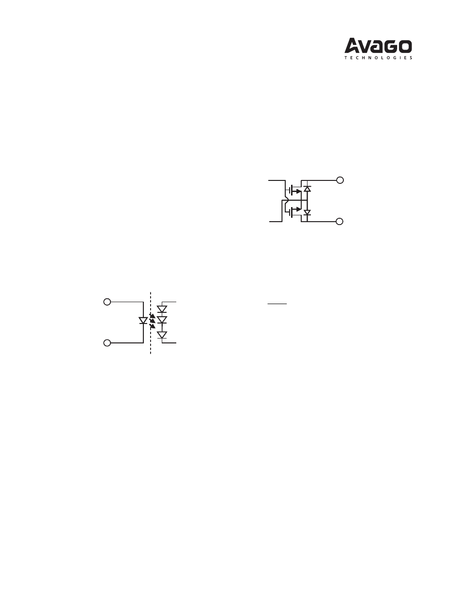
Input
The input channels of the ASSR series are LED driven,
designated as “ANODE” and “CATHODE”.
Figure 2. Output Stage of the ASSR Series
Figure 1. Input Stage of the ASSR Series
They are commonly driven by TTL or buffered CMOS
logic gates. A current limiting resistor at each anode is
usually required to limit the current through the LED
to a proper value. The recommended input forward
current is between 3mA and 20 mA. Thus, if driven by
a 5V power supply, it is recommended to use a resistor
value of 680 ohm. It provides a forward current
between 5mA to 6.5mA where the temperature
variation between -40
0
C to 85
0
C and a 10% tolerance
of the resistor are taken into consideration.
Opto-isolation
Anode
Cathode
-
Drain
Drain
Output
Each output pair of the ASSR Series is made up by two
MOSFET devices with equivalent output voltage rating.
The output traces from the MOSFET drains to the screw
terminals are 50ohm lines, which can withstand 6A,
300Vac.
A load is required at the output port, which limits the
current through the two MOSFET devices. For resistive
load, its resistance should meet
on
D
Load
R
I
V
R
−
≥
max
0
Where,
R
Load
is the resistance of the resistive load,
R
on
is the turn on resistance of the SSR, where R
on
=
6ohm can be used.
V
D
is the voltage applied on the MOSFET drain, and
I
o max
is the recommended maximum output current.