PLANET MC-1500 User Manual
Package contents, Media converter chassis front panel, Product features
- 1 -
- 2 -
- 3 -
- 4 -
- 5 -
- 6 -
- 7 -
- 8 -
1. Package Contents
Before start installing the Converter, verify the package
contains the following parts:
● The Media Converter Chassis x 1
● User's Manual x 1
● Mounting Accessory (for 10/19” Chassis Shelf) x 1
● Rubber Feet x 4
● AC Power Cord x 1
If any of these are missing or damaged, please contact your
dealer immediately, if possible, retain the carton including
the original packing material, and use them against to
repack the product in case there is a need to return it to us
for repair.
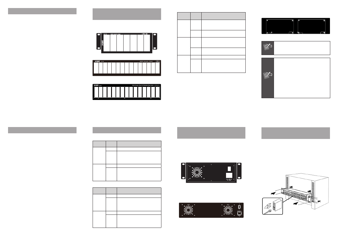
3. Media Converter Chassis Front
Panel
Figure 3-1 & 3-2 & 3-3 shows a front panel of MC-700 /
MC-1500 / MC-1500R / MC-1500R48.
Figure 3-1 MC-700 front panel
Figure 3-2 MC-1500 front panel
Figure 3-3 MC-1500R / 1500R48 front panel
The rear panel of the MC-1500R / 1500R48 is with two
power module slots for redundant power support.
Figure 5-3 MC-1500R / 1500R48 Rear panel
Note
1. The MC-1500R shipped with one 100~240V
AC power supply module (MC-15RPS90).
2. The MC-1500R48 shipped with one DC -
48V power supply module (MC-15RPS48).
Power
Notice
1. The device is a power-required device, it
means, it will not work till it is powered.
If your networks should active all the
time, please consider use a proper UPS
(Uninterrupted Power Supply) for your
device. It will prevent you from network
data loss or network downtime.
2. In some area, installing a surge
suppression device may also help to
protect your chassis from being damaged
by unregulated surge or current to the
converter or the power adapter.
MC-1500R /1500R48
Printing
LED
Status
Description
PWR 1
ON
The chassis is powered by AC power
source (MC-15RPS90) or DC power
source (MC-15RPS48).
OFF
The chassis is not powered or power
failure.
PWR 2
ON
The chassis is powered by AC power
source (MC-15RPS90) or DC power
source (MC-15RPS48).
OFF
The chassis is not powered or power
failure.
FAN A /
FAN B
ON
The fan is functional O.K
OFF
The fan is not powered or it is
malfunction. If the fan LED remains
off while power is on. Please consult
your local dealer to replace the FAN.
2. Product Features
● High quality 10" /19” Rack-Mountable Chassis installation
● Supports up to seven (7) / fifteen (15) hot-swappable
media converters
● One fan brings the air-flow for system cooling, and LED
indicators for system and fan status (MC-700)
● Two fan brings the air-flow for system cooling, and LED
indicators for system and fan status (MC-1500 / 1500R /
1500R48)
● Two power slots at rear panel for redundant power
support with options of 100~240V AC or -48V DC
supplies (MC-1500R / 1500R48)
● Bay power isolation, ensure each bay is electrically
isolated from each other
● Support multiple converters with 10/100/1000Mbps,
copper, Fiber, single/multi-mode ST/SC/SFP connectors
● Reduce the effort of converter maintenance and manage-
ment, diagnose the status at one time
● Cost-effective, easy install
4. LED Indicators
MC-700
Printing
LED
Status
Description
PWR
ON
The chassis is powered.
OFF
The chassis is not powered or power
failure, if the AC outlet is with
100~240V AC voltage. Please consult
your local dealer if power failure.
FAN
ON
The fan is functional ok.
OFF
The fan is not powered or it is
malfunction. If the fan LED remains
off while power is on. Please consult
your local dealer to replace the FAN.
MC-1500
Printing
LED
Status
Description
PWR
ON
The chassis is powered.
OFF
The chassis is not powered or power
failure, if the AC outlet is with
100~240V AC voltage. Please consult
your local dealer if power failure.
FAN A /
FAN B
ON
The fan is functional O.K.
OFF
The fan is not powered or it is
malfunction. If the fan LED remains
off while power is on. Please consult
your local dealer to replace the FAN.
5. Media Converter Chassis Rear
Panel
Figure 5-1 & 5-2 & 5-3 shows a front panel of MC-700 /
MC-1500 / MC-1500R / MC-1500R48.
The rear panel of the MC-700 is with one fan, one ON/
OFF Switch and a power inlet that accept 100~240V AC,
50/60Hz power input.
Figure 5-1 MC-700 Rear panel
The rear panel of the MC-1500 is with two fans, one ON/
OFF Switch and a power inlet that accept 100~240V AC,
50/60Hz power input.
Figure 5-2 MC-1500 Rear panel
6. Installing the Media Converter
Chassis
6.1 Installing Media Converter Chassis to
10/19-inch Wiring Closet Rack
» Install four screws through mounting ears into each side.
» Locate Converter Chassis at 10/19-inch mounting rails
and screw up the front brackets.
» Set Main power switch at
“OFF” position before
connecting the power cord.
Figure 6-1 Installing Media Chassis in Wiring Closet Rails