Appendix a networking connection, A.1 switch‘s rj-45 pin assignments, A.2 rj-45 cable pin assignment – PLANET IFT-802 User Manual
Page 18
Advertising
Appendix A Networking Connection
A.1 Switch‘s RJ-45 Pin Assignments
Contact
MDI
MDI-X
1
1 (TX +)
3
2
2 (TX -)
6
3
3 (RX +)
1
6
6 (RX -)
2
4, 5, 7, 8
Not used
Not used
A.2 RJ-45 cable pin assignment
2 1
3
6
1
2
3
6
2 1
3
6
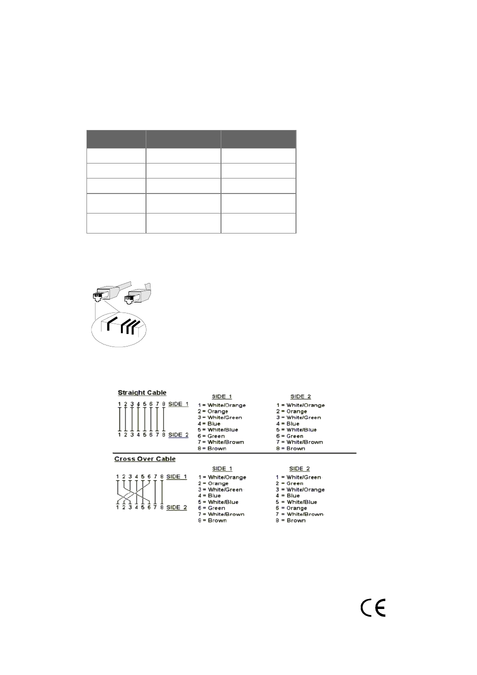
There are 8 wires on a standard UTP/STP cable and each wire is color-coded. The following shows the
pin allocation and color of straight cable and crossover cable connection:
Figure A-1: Straight-Through and Crossover Cable
Please make sure your connected cables are with same pin assignment and color as above picture
before deploying the cables into your network.
2081-AH0010-000
Advertising