ProSoft Technology BM-xx00-RM1K User Manual
Page 40
Advanced User Interface for PC
Page 40 of 48
ProSoft Technology, Inc.
April 21, 2015
9.6
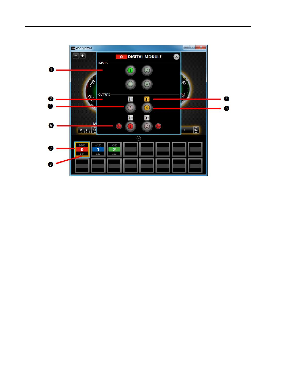
Digital Module Window Guide
1. Digital Input(s) Status: Green = On ; Dimmed = Off
2. Digital Output(s) Status
3. Red LED: displayed when output is normally operated; Dimmed = Off
4. Force Output Button
– click the “F” button
a. Once activated, the user has the option of turning output on or off by pressing on
virtual output buttons.
b. To disable forcing an output, click
“F” again to deactivate force mode.
c. Closing the User Interface or unplugging the mini USB cable will automatically
deactivate any forced output(s).
5. Orange LED: displayed when output is forced on.
6. Displays FailSafe mode that has been set using DIP Switches located on the Digital
Module.
a. In the example shown, DO 1 output will turn on when RF or I/O link fail detected
(Fs indication on).
b. DO 2 output will turn off when RF link fail detected (Fs indication off).
c. DO 3 and 4 will output last known value when RF link fail detected (No Fs
indication).
7. Blue border indicates selected I/O Module.
8. Orange border indicates forced output is active.