Keyboard stand assembly, S 29–31, English 29 – Yamaha P-115 User Manual
Page 29
CLP-115
Keyboard Stand Assembly
ENGLISH
29
Keyboard Stand Assembly
CAUTION
• Be careful not to confuse parts, and be sure to install all parts in the correct direction. Please assemble in accor-
dance with the sequence given below.
• Assembly should be carried out by at least two persons.
• Be sure to use the correct screw size, as indicated below. Use of incorrect screws can cause damage.
• Be sure to tighten up all screws upon completing assembly of each unit.
• To disassemble, reverse the assembly sequence given below.
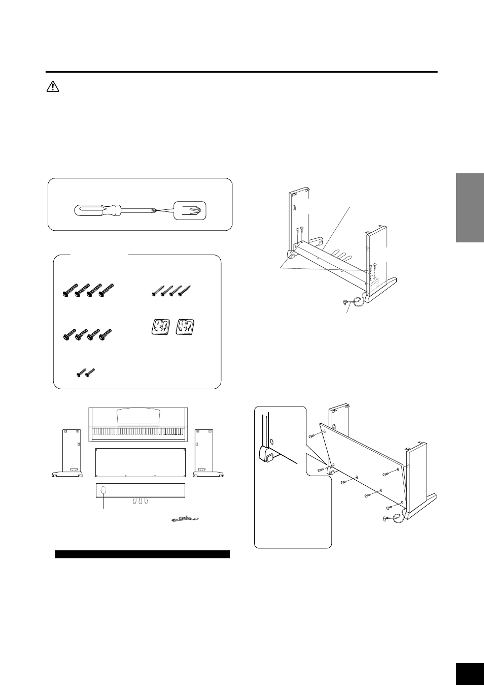
Remove the following parts from the package.
1.
Attach the side panels to the pedal box.
2.
Attach the rear panel.
TIP
A headphone hanger is included in the CLP-115 package.
You can attach a headphone hanger on the CLP-115 to hang
the headphones (page 12).
Have a Phillips-head (+) screwdriver ready
Assembly Parts
6
× 20 mm long screws Ч4
1
4
Ч 12 mm thin screws ×2
3
Cord holders
Ч 2
6
Ч 16 mm short screws Ч4
2
4
Ч 20 mm tapping screws ×4
4
Pedal box
Rear panel
Main unit
Side
panel
(left)
Side
panel
(right)
Bundled pedal
cord inside
AC power cord
L
Side panel
(right)
Side panel
(left)
(1) Untie and straighten out the bun-
dled cord attached to the bottom
of the pedal box.
Don’t discard the twist tie, you’ll
need it later in step 5.
(3) Use the four
6×20 mm long
screws 1 to
attach the
pedal box.
(2) Align the sides of the
pedal box with the left and
right side panels.
R
L
(1) Secure the top of the
rear panel to the side
panel brackets using
two 4×12 mm thin
screws 3.
(2) Secure the bottom of the
rear panel to the pedal box
using four 4×20 mm tapping
screws 4.
Place the bottom edges
of the rear panel on the
feet’s protruding edges,
with the panel slightly
angled as shown in the
illustration.