Check following assembly – KORG LP-380-73 User Manual
Page 18
18
10. Ensure that the stand has no gaps and is not tilted, and that
all the screws are tightened firmly.
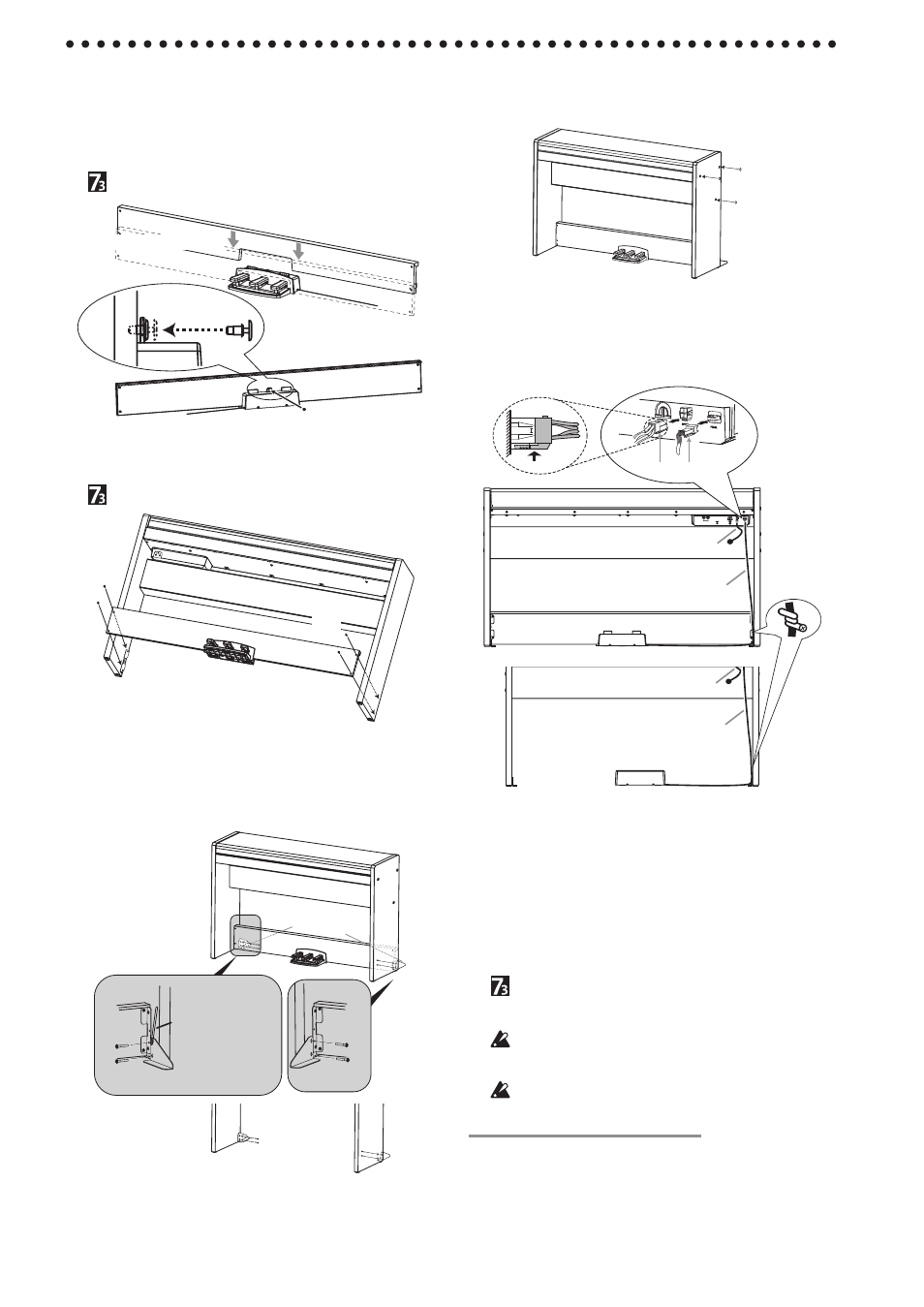
11. Put caps on the screw heads on the right and left side panels.
Caps
12. Connect the pedal cord and the speaker cord to the connec-
tors on the rear of the LP-380’s connector box.
When connecting the pedal cord and the speaker cord, ob-
serve the correct orientations of the connectors.
The pedal cord or the speaker cord can be detached from the
connector with its locking tab held down.
Cord
holder
Speaker cord
Pedal cord
Speaker cord
Pedal cord
Locking tab
73-key version
13. Use the cord holder to hold the pedal cord.
After securing the cord with the cord holder, ensure
that excess pressure is not applied to the connectors.
14. Connect the dedicated cord to the AC adapter. Then,
plug the AC adapter into the DC IN connector, and
wrap the cord around the cord hook of the piano. For
details, refer to “Connecting the Power” on page 5.
15. Place the LP-380 where you intend to use it. Make
sure to place it in a safe location where the floor is flat
and stable.
On the 73-key version, the pedal unit and stand are
separate, and only the pedal cord is attached to the
stand. Be careful when moving the digital piano to an-
other location.
When setting the digital piano in place, make sure that
the stand does not rest on the AC adapter cable or pedal
cable.
For greater safety, be sure to attach the anti-tipping
brackets to the rear of the left and right side panels.
Check following assembly
□ Are any parts left over?
If any parts are left over, carefully review the assembly proce-
dure to see where those parts should have been used.
□ Make sure that all screws are tight.
5. For the 88-key version, insert the pedal unit into the pedal
board, and then fasten it by pressing a push rivet into the
hole (above the cutout) at the rear of the pedal board.
After pressing it into there, lift the pedal board to check that
the pedals do not drop.
The push rivet will prevent the pedal unit from falling out.
Therefore, it cannot be fully fastened to the pedal board.
This step is not necessary with the 73-key version.
Front
Front of pedal board
Rear of pedal board
Rear
Push
Push rivet
6. For the 88-key version, temporarily fasten the pedal board
(with the pedal unit attached) to the hardware inside the
side panels of the stand, using four screws (M4).
This step is not necessary with the 73-key version.
Screws
(M4)
Screws
(M4)
7. Raise the assembled stand slowly with two people.
8. Make sure to attach the anti-tipping brackets behind both
side panels. And the anti-tipping bracket fastened to the
left of the code holder at this time.
Joints between the side panels and the attached anti-tipping
brackets should be even (with no level difference left).
Anti-tipping
Bracket
Screws (M4)
Screws (M4)
Reverse
Reverse
Cord holder
73-key version
9. Then, firmly tighten all the screws that are temporarily
tightened in step 3 and 6.
When tightening the screws on the LP-380, adjust the up/
down and front/rear positions on the left and right side pan-
els so that they are equal.