Rear panel, Panel descriptions, 5v dc connector – Roland Rubix22 2x2 USB Audio Interface User Manual
Page 6: About the usb ac adaptor, Power source] switch, Usb port ( ), Midi (out, in) connectors, Output (1l, 2r, 3l, 4r) jacks (balanced trs type), Ground lift] switch, Loopback] switch
6
Panel Descriptions
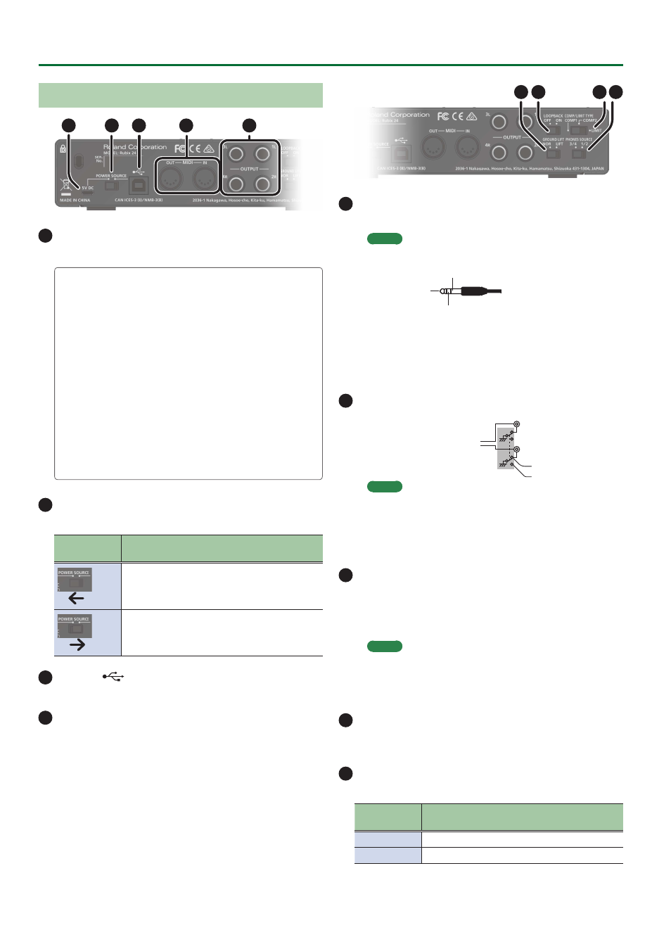
Rear Panel
1
2
5
3
4
1
5V DC connector
Connect this to a commercially available USB AC adaptor.
About the USB AC adaptor
Read the section on
“Using the Unit Safely”
in the manual
included with your USB AC adaptor. Use a USB AC adaptor
that meets the following specifications.
5
USB micro-B type
5
Output voltage: 4.8–5.2 V
5
Output current: 1 A or higher
We have verified that the Rubix operates with typical USB
AC adaptors that meet the above conditions, but cannot
guarantee that it will work with all adaptors that meet these
conditions.
Be aware that even under identical conditions, differences
in the design specifications of a USB AC adaptor and
differences in the conditions of use might make the Rubix
operate or perform differently.
2
[POWER SOURCE] switch
Selects the connector from which power is obtained.
Switch
position
Connector from which power is obtained
5V DC connector (A commercially available USB
adaptor is required.)
USB port (Power is supplied from the connected
computer.)
3
USB port (
)
Connects to the computer.
4
MIDI (OUT, IN) connectors
Connect the MIDI OUT connector to an external MIDI sound
module, etc.
Connect the MIDI IN connector to a MIDI keyboard or MIDI
controller.
7
8 9
6
5
OUTPUT (1L, 2R, 3L, 4R) jacks (balanced TRS type)
Output the analog audio signal.
MEMO
5
Pin assignment of OUTPUT jack
GND (SLEEVE)
HOT (TIP)
COLD (RING)
5
The wiring of this device uses
“impedance balancing.”
The
audio signal is conveyed via HOT and GND in unbalanced
form, but since COLD and GND are connected by a resistor,
the electrical circuit is balanced. This provides the same
noise-reducing effect as a balanced circuit.
6
[GROUND LIFT] switch
OUTPUT (1L, 2R, 3L, 4R)
jacks (balanced TRS
type)
NOR
LIFT
Normally, this switch should
be set to
“NOR”
(NORMAL).
If ground loop noise occurs,
switching this to
“LIFT”
might eliminate the noise.
MEMO
5
The GND (SLEEVE) of the OUTPUT (1L, 2R, 3L, 4R) jacks (TRS
balanced type) is disconnected from ground.
5
In some cases, there might be no sound if you connect a
balanced cable to an unbalanced device and set this switch
to the
“LIFT”
position. If so, set the switch to
“NOR.”
7
[LOOPBACK] switch
If this is turned on, the audio signal that is input to the
INPUT (1L, 2R) jacks is mixed with the audio signal played back from
the computer, and this mixed signal is then sent back (returned) to
the computer. You can use this for live broadcasting to the internet.
MEMO
If you intend to turn the [LOOPBACK] switch on, you should
turn off your DAW software’s monitor function and the
monitoring function of Windows. Failing to do this will cause
oscillation (feedback) or doubling of the input sound.
8
[COMP/LIMIT TYPE] switch
Switches the response of the built-in compressor/limiter circuit
(p. 19).
9
[PHONES SOURCE] switch
Selects the audio signal that is monitored in headphones.
Switch
position
Explanation
1/2
Monitor the output of OUTPUT (1L, 2R).
3/4
Monitor the output of OUTPUT (3L, 4R).