Roland System-500 Series - 531 Mix 6-Channel Mixer - Eurorack Module User Manual
Main specifications, About the manuals, Cv / gate input
English
Owner’s Manual
Before using this unit, carefully read the sections entitled: “USING THE UNIT SAFELY” and “IMPORTANT NOTES” (supplied on a separate sheet).
After reading, keep the document(s) where it will be available for immediate reference.
Copyright © 2018 ROLAND CORPORATION
Model
SYS-555
SYS-505
SYS-510
SYS-531
Current Draw
110 mA (+12 V)
85 mA (-12 V)
85 mA (+12 V)
90 mA (-12 V)
75 mA (+12 V)
60 mA (-12 V)
195 mA (+12 V)
165 mA (-12 V)
Power Supply
Eurorack power
Dimensions
80.8 (W) x 128.5 (D) x 57.2 (H) mm
101.3 (W) x 128.5 (D) x 57.2 (H) mm
3-3/16 (W) x 5-1/16 (D) x 2-1/4 (H) inches
4 (W) x 5-1/16 (D) x 2-1/4 (H) inches
Weight
201 g
191 g
264 g
274 g
8 oz
7 oz
10 oz
10 oz
Accessories
Owner’s Manual, Leaflet “USING THE UNIT SAFELY,” Installation screws (4 pcs.), Eurorack power cable
* This document explains the speci cations of the product at the time that the document was issued. For the latest information, refer to the Roland website.
Main Specifications
Roland SYSTEM-500 (SYS-555, SYS-505, SYS-531, SYS-510) : Eurorack Modular
The documentation for this unit consists of the following materials.
5
USING THE UNIT SAFELY (separate leaflet)
Read this first. It contains notes that you must observe in order to use the unit correctly.
5
Owner’s Manual (this document)
This explains how to make connections, and describes the specifications of the unit.
5
Parameter Guide (English PDF)
This explains the various parts of the unit. Download it as described at right.
About the Manuals
CV stands for “Control Voltage,” an electrical signal (control voltage) that modifies
the behavior of an analog synth or Eurorack module. GATE is a trigger signal that
controls the beginning and end of an envelope or other control voltage.
CV / GATE Input
Use the included screws (4 pcs.) to attach the unit to your Eurorack case at the
locations indicated.
CAUTION
7
Keep small items out of the reach of
children
To prevent accidental ingestion
of the parts listed below, always
keep them out of the reach of small
children.
5
Included Parts: Eurorack installation screws
Installing in a Eurorack Case
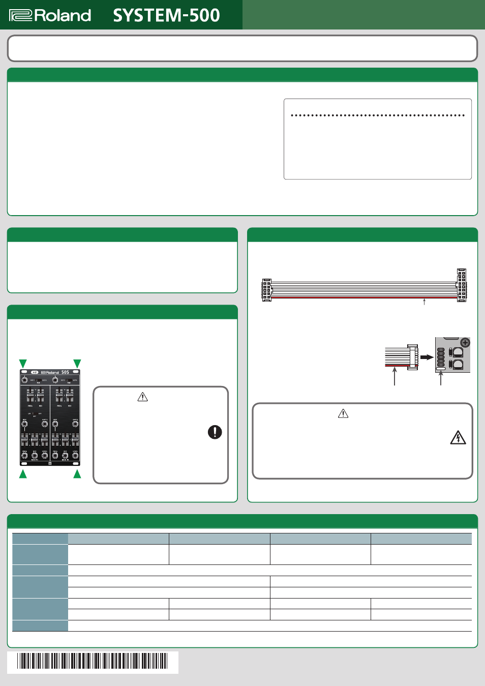
By using the included Eurorack power cable, you can operate this unit on the
Eurorack’s system power supply (±12 V).
1.
Grasp the 16-pin connector of the Eurorack power cable, and insert it into the
Eurorack’s power connector so that the red wire is aligned with the -12 V pin.
2.
Grasp the 10-pin connector of the Eurorack
power cable, and insert it into the unit’s
power connector so that the red wire is
aligned with the white line on the unit.
* Unplug the headphones before turning the power
on or off. Due to the characteristics of the circuitry,
noise might occur at such times.
WARNING
7
Electrocution hazard
* Always turn the Eurorack unit off and unplug the power cord
before plugging the Eurorack power cable.
* Do not touch the electrical terminals when attaching the Eurorack power
cable.
RED SIDE
RED SIDE
WHITE LINE
Using a Eurorack Power Cable
Obtaining the owner’s manual (PDF version)
1.
Enter the following URL on your computer.
https://www.roland.com/support/
2.
On the Support menu, choose “Owner’s Manuals.”
3.
Select the name of your product.
*
5
1
0
0
0
6
1
8
4
6
-
0
1
*