Guided tour, Front panel, Guided tour 5 – Samson Servo 120a Power Amplifier User Manual
Page 5: Front panel 5, Guided tour - front panel, Samson
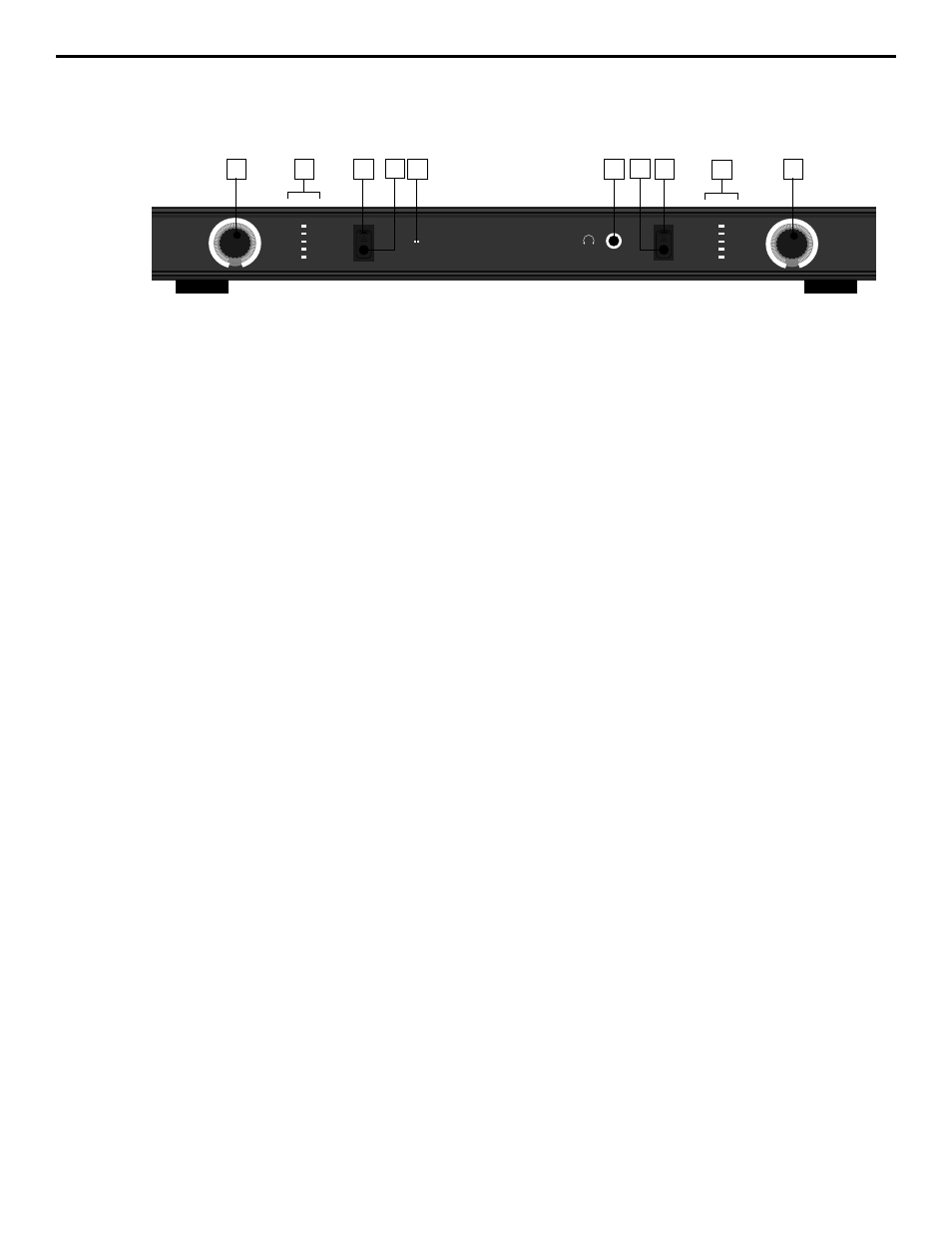
Guided Tour - Front Panel
1: Power switch - Use this to power the Servo120 on or off.
2: Power LED - Lit whenever the Servo 120 is powered on.
3: Channel input level controls - These 41-position detented knobs allow you to adjust the input level
of the signal arriving at the rear-panel input jacks (see #4 and #5 on the following page). At their fully
counterclockwise position (labeled “-70”), the signal is attenuated by 70 dB (essentially completely off).
At their fully clockwise position (labeled “0 dB”), the signal is at unity gain (that is, no attenuation).
When +4 dBu of signal arrives at the input jacks and the Channel input level controls are set to their fully
clockwise “0 dB” position, the Servo 120 delivers full power output.
4: LED meters - These five-segment LED meters continuously monitor the power output level for the
corresponding channel. For convenience, the segments are labeled as follows, from bottom to top:
-16 dB / 15%, -10 dB / 30%, -6 dB / 50%, -3 dB / 70%, and 0 dB / 100%. When the bottom
(-16 dB / 15%) segment is lit, the Servo 120 is operating at approximately 15% of its power capacity.
When the top (0 dB / 100%) segment is lit, signal is being output at full strength. For the best
signal-to-noise ratio, the top (0 dB / 100%) segment should light occasionally during peak levels; if it
lights frequently, you may be overloading the Servo 120 and a distorted (“clipped”) signal is probably
being output. If this occurs and backing off the Input Level control delivers too low an output level for
your application, consider using Bridge mode (see the “Bridge Mode” section on page 7 in this manual
for more information).
5: Protection LED - This goes on for approximately five seconds whenever the Servo120 is powered on
and fades slowly when the amp is powered off. When lit, 0 volts DC are provided to all connected
speakers, thus muting them and preventing any “thump” from occurring. For a complete description of
the conditions under which this light goes on, see the section entitled “The Servo 120 Protection
Circuitry” on page 6 of this manual.
6: Headphone jack - Connect any standard stereo headphones to this jack (via a standard 1/4" TRS
plug) for private monitoring of the final output signal. NOTE: The Servo 120 speaker outputs are not
automatically muted when headphones are inserted into the Headphone jack—to monitor incoming signal
in privacy, press the Speaker on/off switch (see #7 below) so that it is out (in its “up” position)—the
Speaker on/off LED will go off). The built-in Servo 120 headphone amplifier delivers 15 mW into 8 ohms.
7: Speaker on/off switch - When pressed in (the normal position), the Servo 120 delivers signal to its
rear panel output terminals (see #6 on the following page). When this switch is out (in its “up” position),
outgoing signal is muted, allowing personal monitoring of incoming signal through connected
headphones (see #6 above).
8: Speaker on/off LED - Lights when the Speaker on/off switch (see #7 above) is pressed in and the
Servo 120 is delivering signal to its rear panel output terminals (see #6 on the following page).
5
LEVEL
-35
-40
-45
-5
0
-55
-6
0
-65
-70
0dB
-5
-1
0
-15
-2
0
-25
-30
LEVEL
-35
-40
-45
-5
0
-55
-6
0
-65
-70
0dB
-5
-1
0
-15
-2
0
-25
-30
SAMSON
SERVO 120 STEREO AMPLIFIER
100%
70
50
30
15
0dB
-3
-6
-10
-16
POWER
100%
70
50
30
15
0dB
-3
-6
-10
-16
PROTECTION
SPEAKER
2
1
3
4
5
6
7
8
4
3