Zrct-300 display controller – Sony ZRD-B12A Micro LED Video Wall Modular Display User Manual
Page 9
9
TEST switch (ZRD-CH12D/ZRD-CH15D/ZRD-
BH12D/ZRD-BH15D only)
By using the switch, the test pattern can be
displayed without connecting the controller.
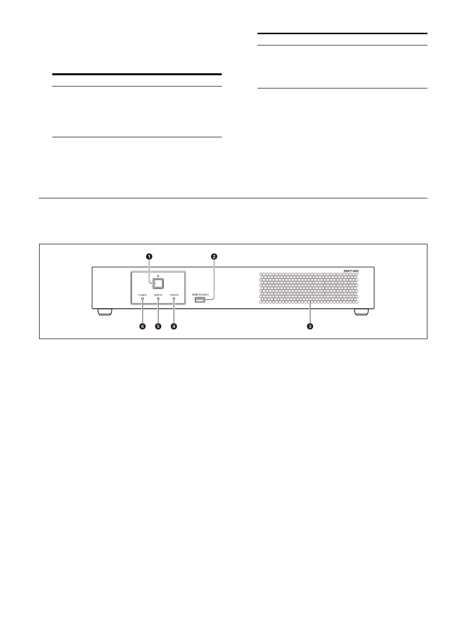
ZRCT-300 Display Controller
Front
(power) switch
Turns the Display Controller on/off.
For details, see “Turning the Power On/
Off” (page 11).
MAINTENANCE connector (USB, Type A)
This connector is used for maintenance
servicing.
Intake vent
Do not block the intake vent, as doing so will
result in interior heat buildup which may
result in fire or malfunction.
ERROR indicator
Blinks when warnings occur, and lights when
errors occur.
For details, see “Troubleshooting”
(page 27) and “Error Codes” (page 29).
STATUS indicator
Indicates the power status of the Display
Cabinets.
The indicator lights green when all the
Display Cabinets that are connected to the
Display Controller according to the Display
Cabinet layout settings are turned on.
If any of the Display Cabinets are turned off
according to the Display Cabinet layout
settings, the indicator turns off.
For details on the Display Cabinet layout
settings, consult your system
administrator.
Operation
Description
Press and hold
While in standby mode:
Turns the power on and
displays the test pattern.
When the power is turned
on: Goes into standby
mode.
Press
While in standby mode:
None
When the power is turned
on: Changes the test
pattern.
Operation
Description