Sony SRS-XE300 Portable Bluetooth Speaker (Blue) User Manual
Shoe mount adaptor, Smad-p5, 使用上のご注意
SMAD-P5 5-010-055-01(1)
5-010-055-
01
(1)
Shoe Mount Adaptor
Istruzioni per l’uso
Operating Instructions
Manual de instrucciones
Mode d’emploi
Bedienungsanleitung
ˎ
ˎ
UWP-D
ˎ
ˎ
ˎ
ˎ
Digital
1 k
1.16
Digital
0
50
20
55
34 mm 35 mm 65 mm
27 g
1
1
English
L-2_v005-000_5-010-055-01(1)_201906181309_GB_1/13
Before operating the unit, please read this manual thoroughly and retain
it for future reference.
L-1A_v001-000_5-010-055-01(1)_201906181309_GB_2/13
WARNING
To reduce the risk of fire or electric shock, do not expose this
apparatus to rain or moisture.
To avoid electrical shock, do not open the cabinet. Refer servicing to
qualified personnel only.
S-1_v007-000_5-010-055-01(1)_201906181309_GB_3/13
For the customers in the U.S.A.
This equipment has been tested and found to comply with the limits
for a Class B digital device, pursuant to part 15 of the FCC Rules. These
limits are designed to provide reasonable protection against harmful
interference in a residential installation. This equipment generates, uses
and can radiate radio frequency energy and, if not installed and used
in accordance with the instructions, may cause harmful interference to
radio communications. However, there is no guarantee that interference
will not occur in a particular installation. If this equipment does cause
harmful interference to radio or television reception, which can be
determined by turning the equipment off and on, the user is encouraged
to try to correct the interference by one or more of the following
measures:
• Reorient or relocate the receiving antenna.
• Increase the separation between the equipment and receiver.
• Connect the equipment into an outlet on a circuit different from that
to which the receiver is connected.
• Consult the dealer or an experienced radio/TV technician for help.
E-6_v003-000_5-010-055-01(1)_201906181309_GB_4/13
You are cautioned that any changes or modifications not expressly
approved in this manual could void your authority to operate this
equipment.
E-7_v002-000_5-010-055-01(1)_201906181309_GB_5/13
If you have any questions about this product, you may call:
Sony Customer Information Service Center 1-800-222-7669 or http://
www.sony.com/
Supplier’s Declaration of Conformity
Trade Name
: SONY
Model
: SMAD-P5
Responsible party
: Sony Electronics Inc.
Address
: 16535 Via Esprillo, San Diego, CA
92127 U.S.A.
Telephone Number
: 858-942-2230
This device complies with part 15 of the FCC Rules. Operation is subject
to the following two conditions: (1) This device may not cause harmful
interference, and (2) this device must accept any interference received,
including interference that may cause undesired operation.
E-10A_v002-000_5-010-055-01(1)_201906181309_GB_6/13
For the customers in Canada
CAN ICES-3 (B)/NMB-3(B)
E-13_v002-000_5-010-055-01(1)_201906181309_GB_7/13
ATTENTION
The electromagnetic fields at the specific frequencies may influence the
sound of this unit.
E-24B_v008-000_5-010-055-01(1)_201906181309_GB_8/13
Türkiye’deki müşteriler için
AEEE Yönetmeliğine Uygundur
K-T4-2_v004--001_5-010-055-01(1)_201906181309_TR_9/13
For the customers in the U.S.A.
SONY LIMITED WARRANTY- Please visit http://www.sony.com/psa/
warranty for important information and complete terms and conditions
of Sony’s limited warranty applicable to this product.
For the customers in Canada
SONY LIMITED WARRANTY - Please visit http://www.sonybiz.ca/pro/
lang/en/ca/article/resources-warranty for important information and
complete terms and conditions of Sony’s limited warranty applicable to
this product.
For the customers in Europe
Sony Professional Solutions Europe - Standard Warranty and Exceptions
on Standard Warranty. Please visit http://www.pro.sony.eu/warranty
for important information and complete terms and conditions.
For the customers in Korea
SONY LIMITED WARRANTY - Please visit http://bpeng.sony.co.kr/
handler/BPAS-Start for important information and complete terms and
conditions of Sony’s limited warranty applicable to this product.
L-5_v003-000_5-010-055-01(1)_201906181309_GB_10/13
Usage Precautions
M-0010_v001-000_5-010-055-01(1)_201906181309_GB_11/13
Notes
• Always verify that the unit is operating properly before use. SONY
WILL NOT BE LIABLE FOR DAMAGES OF ANY KIND INCLUDING,
BUT NOT LIMITED TO, COMPENSATION OR REIMBURSEMENT ON
ACCOUNT OF THE LOSS OF PRESENT OR PROSPECTIVE PROFITS DUE
TO FAILURE OF THIS UNIT, EITHER DURING THE WARRANTY PERIOD
OR AFTER EXPIRATION OF THE WARRANTY, OR FOR ANY OTHER
REASON WHATSOEVER.
• SONY WILL NOT BE LIABLE FOR CLAIMS OF ANY KIND MADE BY
USERS OF THIS UNIT OR MADE BY THIRD PARTIES.
• SONY WILL NOT BE LIABLE FOR THE TERMINATION OR
DISCONTINUATION OF ANY SERVICES RELATED TO THIS UNIT THAT
MAY RESULT DUE TO CIRCUMSTANCES OF ANY KIND.
M-A120-00_v003-000_5-010-055-01(1)_201906181309_GB_12/13
If the unit is suddenly taken from a cold to a warm location, or if ambient
temperature suddenly rises, moisture may form on the outer surface
of the unit and/or inside of the unit. This is known as condensation. If
condensation occurs, turn off the unit and wait until the condensation
clears before operating the unit. Operating the unit while condensation
is present may damage the unit.
M-B200-00_v005-000_5-010-055-01(1)_201906181309_GB_13/13
ˎ
ˎ
Noise may occur in some rare cases due to signal interference from mobile
terminals.
To prevent noise, operate the unit at least 30 cm away from any mobile terminals.
ˎ
ˎ
When using this unit, do not connect the receiver’s output cables to the camera.
Doing so may result in noise.
Overview
This unit is a dedicated shoe-mount adaptor used for connecting the UWP-D
series wireless microphone package’s receiver (URX-P40 portable diversity tuner)
to a camera.
The adaptor supports video camera recorders and interchangeable-lens digital
cameras from Sony and other Sony cameras equipped with a multi-interface shoe,
improving the convenience of using a wireless microphone for shooting video.
ˎ
ˎ
Wirelessly transfer audio signals from the receiver to the camera.
ˎ
ˎ
Connects directly to a camera equipped with a multi-interface shoe that
supports digital audio input for recording of a digital audio signal output from
a receiver, enabling the recording of low-noise audio.
ˎ
ˎ
Supports the display of the status of the wireless microphone on the LCD
screen or viewfinder for some models.
ˎ
ˎ
Provides power from the camera to the receiver via settings on the receiver.
ˎ
ˎ
Power supply automatically switches to power from the camera when
batteries are not inserted in the receiver. In such cases, on/off switching of the
receiver’s power is linked to that of the camera.
Note
When used in conjunction with some camera models, operation of the power
supply function and the power ON/OFF control function is not guaranteed. Insert
new AA alkaline batteries in the receiver, and set the receiver’s power select
(PWR SOURCE) menu item to BATT ONLY mode. When the remaining battery
indicator reaches one segment or less, insert new batteries immediately to avoid
unexpected shutdown of the camera or data loss.
For details on cameras that support this unit, visit the Sony website.
Parts Identification (Fig.
)
Receiver connection terminal
Guide
Tightening dial
Multi-interface foot
Terminal cap
Receiver tightening dial
Analog/Digital switch
Attaching/Removing the Receiver (Fig.
)
Align the guide of the unit with the hole on the receiver, and insert into the
receiver so that the connector of the unit and the connector on the rear of the
receiver are firmly connected. Then, turn the receiver tightening dial while
holding the receiver firmly to secure the receiver.
Be sure to remove the unit from the camera before removing the receiver.
Mounting to the Camera (Fig.
)
1.
Remove the terminal cap.
2.
Turn off the camera, align the unit’s multi-interface foot with the camera’s
multi-interface shoe, and slide the unit in toward the lens until it is secure.
Note
Mounting may be difficult when performed with the tightening dial turned
toward the LOCK arrow. Turn the tightening dial in the opposite direction of
the LOCK arrow before mounting.
3.
Turn the tightening dial in the direction of the LOCK arrow to secure the unit.
When removing the unit, turn the camera off before performing the above
procedure in reverse order.
Note
If the unit is attached to the handle of the camera handle, make sure that no load
is placed on the unit and receiver.
Linking the Receiver Power to the Camera
You can link the on/off switching of the camera’s power to that of the receiver.
Perform the following while the unit and the receiver are connected to the
camera.
1.
Remove the LR6 (size AA) batteries from the receiver.
2.
Turn on the camera.
3.
Turn on the receiver.
Notes
ˎ
ˎ
If you turn off the power via the receiver, its link with the camera will be
severed. To reestablish the link, operate the receiver to turn it on.
ˎ
ˎ
If BATT ONLY is set in the power source selection menu of the receiver, it cannot
be linked with the camera.
Switching the Output Signal
You can change the type of audio signal that is output from the unit using the
Analog/Digital switch. It is set to Analog when shipped from the factory.
Analog
: The adaptor supports existing video camera recorders and
interchangeable-lens digital cameras from Sony and other Sony cameras
equipped with a multi-interface shoe.
Digital
: The adaptor supports cameras equipped with a multi-interface shoe
that supports digital audio input. For some models, the RF level meter of
the receiver, muting status of the transmitter (M mark), and remaining
battery capacity warning (RF level meter flashes) are displayed on the
LCD screen or viewfinder (see the following table).
For details on cameras that support this function, visit the Sony website.
Note
When attached to cameras that do not support digital audio input, set the
Analog/Digital switch to the Analog position for use. If the Analog/Digital switch
is set to the Digital position, the audio signal will not be output to the camera.
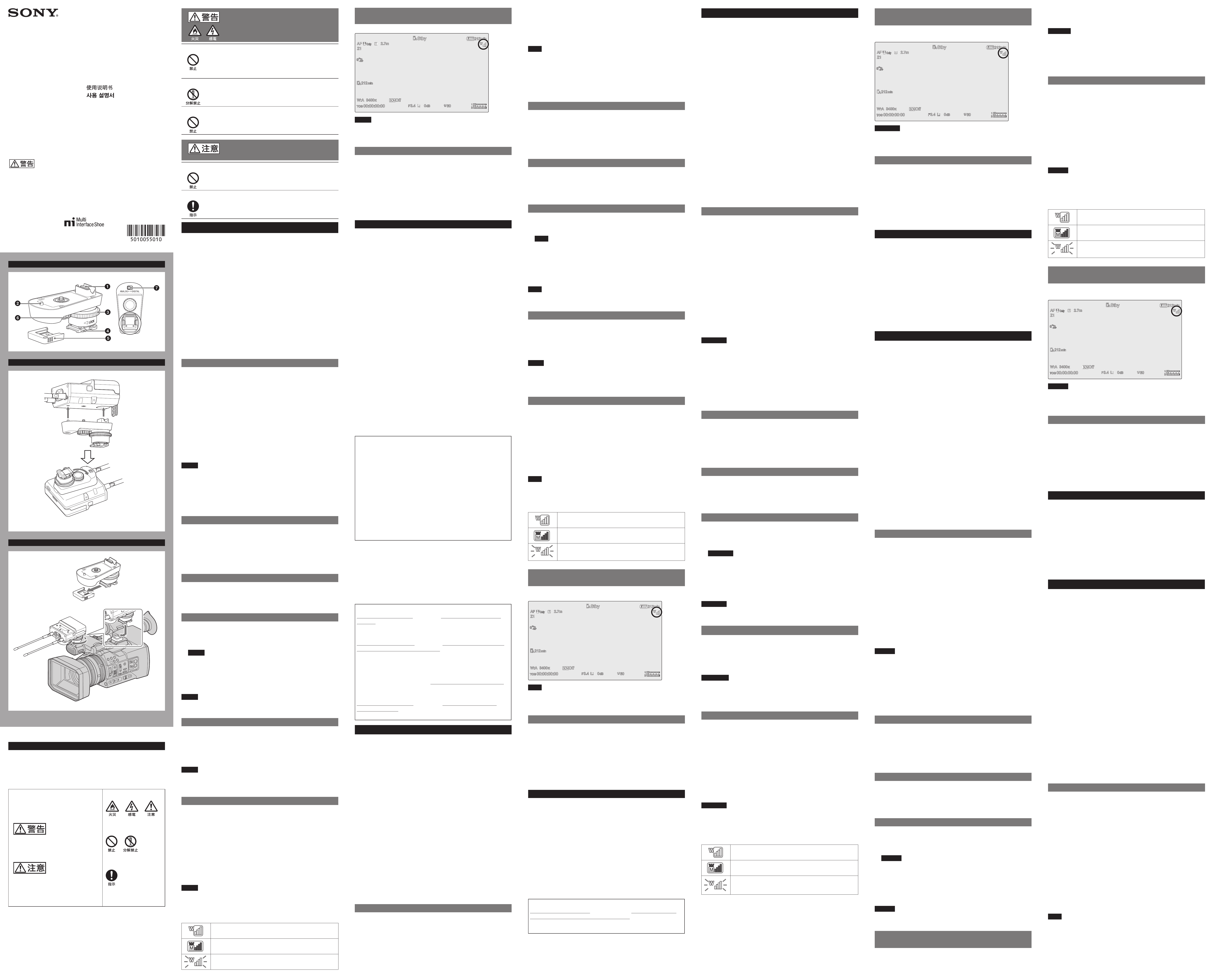
Icons displayed when the output signal type is set to Digital
Indicates the current reception level status.
Indicates the transmitter is in muting state.
Indicates the remaining battery capacity of the transmitter is low
when flashing.
LCD Screen/Viewfinder Icon Display Position
Example
When the output signal is set to Digital, the icon is displayed enclosed by a
border.
Note
The display position and display form of the icon on the LCD screen or viewfinder
will vary depending on the camera. For details, refer to the operating instructions
of the attached camera.
Specifications
Output impedance
1 kΩ or less
Audio delay
Approx. 1.16 ms (Digital)
Operating temperature
0 °C to 50 °C (32 °F to 122 °F)
Storage temperature
–20 °C to +55 °C (–4 °F to +131 °F)
Dimensions
Approx. 34 mm × 35 mm × 65 mm
(1
3
/
8
in. × 1
7
/
16
in. × 2
5
/
8
in.) (w/h/d)
Mass
Approx. 27 g (1.0 oz.) (excluding terminal cap)
Supplied accessories
Operating Instructions (1) (this document)
Warranty booklet (1)
Design and specifications are subject to change without notice.
Français
L-2_v005-000_5-010-055-01(1)_201906181309_FR_1/9
Avant d’utiliser l’appareil, veuillez lire attentivement ce manuel et le
conserver pour future référence.
L-1A_v001-000_5-010-055-01(1)_201906181309_FR_2/9
AVERTISSEMENT
Afin de réduire les risques d’incendie ou d’électrocution, ne pas
exposer cet appareil à la pluie ou à l’humidité.
Afin d’écarter tout risque d’électrocution, garder le coffret fermé. Ne
confier l’entretien de l’appareil qu’à un personnel qualifié.
S-1_v007-000_5-010-055-01(1)_201906181309_FR_3/9
Pour les clients au Canada
CAN ICES-3 (B)/NMB-3(B)
E-13_v002-000_5-010-055-01(1)_201906181309_FR_4/9
ATTENTION
Il est possible que des champs électromagnétiques à des fréquences
spécifiques influencent le son de cet appareil.
E-24B_v008-000_5-010-055-01(1)_201906181309_FR_5/9
Pour les clients au Canada
GARANTIE LIMITÉE DE SONY - Rendez-vous sur http://www.sonybiz.
ca/pro/lang/en/ca/article/resources-warranty pour obtenir les
informations importantes et l’ensemble des termes et conditions de la
garantie limitée de Sony applicable à ce produit.
L-6_v004-000_5-010-055-01(1)_201906181309_FR_6/9
DC
使用上のご注意
M-0010_v001-000_5-010-055-01(1)_201906181309_JP_1/3
• お使いになる前に、必ず動作確認を行ってください。故障その他に伴う営業
上の機会損失等は保証期間中および保証期間経過後にかかわらず、補償はい
たしかねますのでご了承ください。
• 本製品を使用したことによるお客様、または第三者からのいかなる請求につ
いても、当社は一切の責任を負いかねます。
• 諸事情による本製品に関連するサービスの停止、中断について、一切の責任を
負いかねます。
M-A120-00_v003-000_5-010-055-01(1)_201906181309_JP_2/3
本機を寒いところから急に暖かいところに持ち込んだときなど、機器表面や内部に
水滴がつくことがあります。これを結露といいます。結露が起きたときは電源を
切り、結露がなくなるまで放置し、結露がなくなってからご使用ください。結露時
のご使用は機器の故障の原因となる場合があります。
M-B200-00_v005-000_5-010-055-01(1)_201906181309_JP_3/3
ˎ
ˎ
30 cm
ˎ
ˎ
UWP-D
URX-P40
ˎ
ˎ
ˎ
ˎ
ˎ
ˎ
ˎ
ˎ
ˎ
ˎ
3
PWR SOURCE
BATT ONLY
1
ˎ
˜
ˎ
ˎˎ
ˎˎ
ˎ
ˎˎ
ˎˎ
Analog/Digital
1.
2.
LOCK
LOCK
3.
LOCK
1.
3
2.
3.
ˎ
ˎ
ˎ
ˎ
BATT ONLY
Analog/Digital
Analog
Analog
Digital
RF
M
RF
ˎ
˜
WEB
Analog/Digital
Analog
Analog/Digital
Digital
Digital
SMAD-P5
© 2019 Sony Corporation
Printed in Korea
A
B
C
3
2
1
Précautions d’utilisation
M-0010_v001-000_5-010-055-01(1)_201906181309_FR_7/9
Remarques
• Vérifiez toujours que l’appareil fonctionne correctement avant
l’utilisation. Sony n’assumera pas de responsabilité pour les
dommages de quelque sorte qu’ils soient, incluant mais ne se
limitant pas à la compensation ou au remboursement, à cause de
la perte de profits actuels ou futurs suite à la défaillance de cet
appareil, que ce soit pendant la période de garantie ou après son
expiration, ou pour toute autre raison quelle qu’elle soit.
• Sony n’assumera pas de responsabilité pour les réclamations, quelle
qu’elles soient, effectuées par les utilisateurs de cet appareil ou par
des tierces parties.
• Sony n’assumera pas de responsabilité pour la cessation ou
l’interruption de tout service liй а cet appareil, résultant de quelque
circonstance que ce soit.
M-A120-00_v003-000_5-010-055-01(1)_201906181309_FR_8/9
Si l’appareil est soudainement déplacé d’un endroit froid à un endroit
chaud, ou si la température ambiante augmente brusquement, de
l’humidité peut se former sur la surface externe de l’appareil et/ou
à l’intérieur de l’appareil. Ce phénomène est connu sous le nom de
condensation. Si de la condensation se produit, mettez l’appareil hors
tension et patientez le temps que la condensation disparaisse avant
d’utiliser l’appareil. L’utilisation de l’appareil avec de la condensation
pourrait endommager l’appareil.
M-B200-00_v005-000_5-010-055-01(1)_201906181309_FR_9/9
ˎ
ˎ
Dans de rares cas, du bruit peut se produire en raison des interférences de
signal provenant de terminaux mobiles.
Afin d’éviter ce bruit, faites fonctionner l’appareil à au moins 30 cm de tout
terminal mobile.
ˎ
ˎ
Lorsque vous utilisez cet appareil, ne connectez pas les câbles de sortie du
récepteur à la caméra. Sinon, cela pourrait générer du bruit.
Aperçu
Cet appareil est un adaptateur de caméra dédié utilisé pour la connexion du
récepteur de l’ensemble microphone sans fil de la série UWP-D (tuner à diversité
portable URX-P40) à la caméra.
L’adaptateur prend en charge les enregistreurs de caméra vidéo et les caméras
numériques à objectif interchangeable de Sony et ainsi que d’autres caméras
Sony équipées d’un adaptateur multi-interface, permettant ainsi un meilleur
confort grâce à l’utilisation d’un microphone sans fil pour la prise de vue vidéo.
ˎ
ˎ
Transférer sans fil des signaux audio du récepteur à la caméra.
ˎ
ˎ
Connecte directement une caméra équipée d’un adaptateur multi-interface
qui prend en charge l’entrée audio numérique pour l’enregistrement
d’un signal audio numérique émis par un récepteur, permettant ainsi
l’enregistrement d’un son à faible bruit parasite.
ˎ
ˎ
Prend en charge l’affichage de l’état du microphone sans fil sur l’écran LCD ou
le viseur sur certains modèles.
ˎ
ˎ
Fournir l’alimentation de la caméra au récepteur par le biais des réglages sur
le récepteur.
ˎ
ˎ
L’alimentation électrique passe automatiquement à l’alimentation de la
caméra lorsque les piles ne sont pas insérées dans le récepteur. Dans ce cas,
la commutation on/off de l’alimentation du récepteur est liée à celle de la
caméra.
Remarque
En cas d’utilisation conjointe avec certains modèles de caméra, le
fonctionnement de la fonction d’alimentation électrique et de la fonction de
contrôle d’activation/désactivation (ON/OFF) d’alimentation n’est pas garanti.
Insérez deux piles alcalines AA neuves dans le récepteur et réglez l’option de
menu pour la sélection de l’alimentation (PWR SOURCE) du récepteur sur le
mode BATT ONLY. Lorsque l’indicateur d’état de charge restante atteint un
segment ou moins, insérez immédiatement les piles neuves pour éviter un arrêt
inattendu de la caméra ou une perte de données.
Pour les détails sur les caméras compatibles avec cet appareil, visitez le site web de
Sony.
Nomenclature (Fig.
)
Terminal de connexion du récepteur
Guide
Molette de serrage
Pédale multi-interface
Cache terminal
Molette de serrage de récepteur
Commutateur Analog/Digital
Fixation/Retrait du récepteur (Fig.
)
Alignez le guide de l’appareil avec l’orifice sur le récepteur, et insérez-le dans le
récepteur de sorte que le connecteur de l’appareil et le connecteur sur l’arrière
du récepteur soient fermement connectés. Tournez, ensuite, la molette de
serrage du récepteur tout en tenant fermement le récepteur pour le serrer.
Assurez-vous de retirer l’appareil de la caméra avant de retirer le récepteur.
Montage de la caméra (Fig.
)
1.
Retirez le cache terminal.
2.
Mettez la caméra hors tension, alignez la pédale multi-interface de l’appareil
avec l’adaptateur multi-interface de la caméra et glissez l’appareil vers
l’objectif jusqu’à ce qu’il soit serré.
Remarque
Le montage peut s’avérer difficile s’il est effectué avec la molette de serrage
tournée vers la flèche LOCK. Tournez la molette de serrage dans le sens
contraire de la flèche LOCK avant le montage.
3.
Tournez la molette de serrage dans le sens de la flèche LOCK pour serrer l’appareil.
Lors du retrait de l’appareil, mettez la caméra hors tension avant d’effectuer la
procédure ci-dessus dans l’ordre inverse.
Remarque
Si l’appareil est fixé à la poignée de la poignée de caméra, assurez-vous
qu’aucune charge n’est placée sur l’appareil et le récepteur.
Liaison de l’alimentation du récepteur à la caméra
Vous pouvez lier la commutation on/off de la caméra à celle du récepteur.
Effectuez la procédure suivante lorsque l’appareil et le récepteur sont raccordés
à la caméra.
1.
Retirez les piles LR6 (format AA) du récepteur.
2.
Mettez la caméra sous tension.
3.
Mettez le récepteur sous tension.
Remarques
ˎ
ˎ
Si vous mettez l’appareil hors tension via le récepteur, le lien avec la caméra sera
coupé. Pour rétablir le lien, utilisez le récepteur pour le mettre sous tension.
ˎ
ˎ
Si BATT ONLY est réglé dans le menu de sélection de la source d’alimentation
du récepteur, l’appareil ne peut pas être liй а la caméra.
Commutation du signal de sortie
Vous pouvez modifier le type de signal audio émis par l’appareil à l’aide du
commutateur Analog/Digital. Cela est réglé sur Analog au départ de l’usine.
Analog
: L’adaptateur prend en charge les enregistreurs de caméra vidéo et les
caméras numériques à objectif interchangeable de Sony et ainsi que
d’autres caméras Sony équipées d’un adaptateur multi-interface.
Digital
: L’adaptateur prend en charge les caméras équipées d’un adaptateur
multi-interface prenant en charge l’entrée audio numérique. Pour
certains modèles, l’indicateur de niveau RF du récepteur, l’état silencieux
de l’émetteur (repère M), et l’avertissement de charge restante
(l’indicateur de niveau RF clignote) sont affichés sur l’écran LCD ou le
viseur (consultez le tableau suivant).
Pour plus de détails sur les caméras qui prennent en charge cette fonction, visitez le
site Web de Sony.
Remarque
Lorsque l’appareil est connecté à des caméras qui ne prennent pas en charge
l’entrée audio numérique, placez le commutateur Analog/Digital sur la position
Analog pour pouvoir l’utiliser. Si le commutateur Analog/Digital est placé sur la
position Digital, le signal audio ne sera pas émis vers la caméra.
Icônes affichées lorsque le type de signal de sortie est réglé sur Digital
Indique l’état du niveau de réception actuel.
Indique que l’émetteur est en mode silencieux.
Indique par un clignotement que la charge restante de la pile de
l’émetteur est faible.
Exemple de position d’affichage de l’icône de
l’écran LCD/du viseur
Lorsque le signal de sortie est réglé sur Digital, l’icône est affichée entourée d’un
bord .
Remarque
La position et la forme de l’affichage de l’icône sur l’écran LCD ou le viseur
varient en fonction de la caméra. Pour plus de détails, consultez le mode
d’emploi de la caméra installée.
Spécifications
Impédance de sortie
1 kΩ ou moins
Décalage audio
Env. 1,16 ms (Numérique)
Température de fonctionnement 0 °C à 50 °C (32 °F à 122 °F)
Température de stockage
–20 °C à +55 °C (–4 °F à +131 °F)
Dimensions
Env. 34 mm × 35 mm × 65 mm
(1
3
/
8
po. × 1
7
/
16
po. × 2
5
/
8
po.) (l/h/p)
Poids
Env. 27 g (1,0 on.) (hors cache terminal)
Accessoires fournis
Mode d’emploi (1) (ce document)
Livret de garantie (1)
La conception et les spécifications sont sujettes à des modifications sans préavis.
Deutsch
L-2_v005-000_5-010-055-01(1)_201906181309_DE_1/7
Bitte lesen Sie dieses Handbuch vor der Benutzung des Geräts sorgfältig
durch und bewahren Sie es zum späteren Nachschlagen auf.
L-1A_v001-000_5-010-055-01(1)_201906181309_DE_2/7
WARNUNG
Um die Gefahr von Bränden oder elektrischen Schlägen zu
verringern, darf dieses Gerät nicht Regen oder Feuchtigkeit
ausgesetzt werden.
Um einen elektrischen Schlag zu vermeiden, darf das Gehäuse
nicht geöffnet werden. Überlassen Sie Wartungsarbeiten stets nur
qualifiziertem Fachpersonal.
S-1_v007-000_5-010-055-01(1)_201906181309_DE_3/7
ACHTUNG
Die elektromagnetischen Felder bei den speziellen Frequenzen können
den Ton dieses Geräts beeinflussen.
E-24B_v008-000_5-010-055-01(1)_201906181309_DE_4/7
Vorsichtsmaßnahmen bei der Verwendung
M-0010_v001-000_5-010-055-01(1)_201906181309_DE_5/7
Hinweise
• Bestätigen Sie vor dem Gebrauch immer, dass das Gerät richtig
arbeitet. SONY KANN KEINE HAFTUNG FÜR SCHÄDEN JEDER ART,
EINSCHLIESSLICH ABER NICHT BEGRENZT AUF KOMPENSATION ODER
ERSTATTUNG, AUFGRUND VON VERLUST VON AKTUELLEN ODER
ERWARTETEN PROFITEN DURCH FEHLFUNKTION DIESES GERÄTS
ODER AUS JEGLICHEM ANDEREN GRUND, ENTWEDER WÄHREND
DER GARANTIEFRIST ODER NACH ABLAUF DER GARANTIEFRIST,
ÜBERNEHMEN.
• SONY KANN KEINE HAFTUNG FÜR ANSPRÜCHE JEDER ART VON
DEN BENUTZERN DIESES GERÄTS ODER VON DRITTER SEITE
ÜBERNEHMEN.
• SONY KANN KEINE HAFTUNG FÜR DIE BEENDIGUNG ODER
EINSTELLUNG VON DIENSTLEISTUNGEN BEZÜGLICH DIESES GERÄTS
GLEICH AUS WELCHEM GRUND ÜBERNEHMEN.
M-A120-00_v003-000_5-010-055-01(1)_201906181309_DE_6/7
Wenn das Gerät aus einer kalten Umgebung in einen warmen Raum
gebracht wird oder die Umgebungstemperatur schnell ansteigt,
kann sich auf der Oberfläche des Geräts bzw. im Inneren des Geräts
Feuchtigkeit ansammeln (Kondensation). Schalten Sie in diesem Fall
das Gerät aus, und warten Sie, bis die Kondensation verdunstet ist, ehe
Sie das Gerät verwenden. Die Verwendung des Gerätes bei gebildetem
Kondenswasser kann zu Beschädigungen führen.
M-B200-00_v005-000_5-010-055-01(1)_201906181309_DE_7/7
ˎ
ˎ
Durch Signalstörungen von mobilen Endgeräten können in seltenen Fällen
Geräusche auftreten.
Um Geräusche zu vermeiden, betreiben Sie das Gerät mindestens 30 cm von
mobilen Endgeräten entfernt.
ˎ
ˎ
Wenn Sie dieses Gerät benutzen, schließen Sie die Ausgangskabel des
Empfängers nicht an die Kamera an. Andernfalls können Störgeräusche auftreten.
Übersicht
Dieses Gerät ist ein spezieller Kontaktschuhadapter, mit dem der Empfänger aus
dem Funkmikrofonpaket der UWP-D-Serie (mobiler Diversity-Tuner URX-P40) an
eine Kamera angeschlossen wird.
Der Adapter unterstützt Videocamcorder und digitale Kameras von Sony mit
Wechselobjektiv sowie andere Sony-Kameras mit Multi-Interface-Zubehörschuh
und erleichtert die Verwendung eines Funkmikrofons für Videoaufnahmen.
ˎ
ˎ
Übertragen Sie drahtlos Audiosignale vom Empfänger auf die Kamera.
ˎ
ˎ
Direkter Anschluss an Kameras mit Multi-Interface-Zubehörschuh, der
die digitale Audioeingabe zur Aufzeichnung eines von einem Empfänger
ausgegebenen digitalen Audiosignals unterstützt und so rauscharme
Audioaufnahmen ermöglicht.
ˎ
ˎ
Unterstützt bei einigen Modellen die Anzeige des Status des Funkmikrofons
auf dem LCD-Bildschirm oder Sucher.
ˎ
ˎ
Versorgen Sie den Empfänger von der Kamera aus über Einstellungen am
Empfänger mit Strom.
ˎ
ˎ
Die Stromversorgung wechselt automatisch zur Stromversorgung durch die
Kamera, wenn im Empfänger keine Akkus eingelegt sind. In solchen Fällen
wird der Empfänger gemeinsam mit der Kamera ein- und ausgeschaltet.
Hinweis
In Verbindung mit einigen Kameramodellen werden der Betrieb der
Stromversorgungsfunktion sowie der Ein-/Ausschalter-Funktion nicht garantiert.
Legen Sie neue Alkaline-Batterien (Größe AA) in den Empfänger ein und stellen
Sie die Menüoption PWR SOURCE (Auswahl des Stromversorgungsmodus) auf
BATT ONLY. Wenn die Anzeige der verbleibenden Batteriekapazität ein Segment
oder weniger erreicht, legen Sie sofort neue Batterien ein, um ein unerwartetes
Herunterfahren der Kamera oder Datenverlust zu vermeiden.
Weitere Informationen zu Kameras, die dieses Gerät unterstützen, finden Sie auf der
Website von Sony.
Beschreibung der Teile (Abb.
)
Empfängeranschluss
Führung
Feststellrad
Multi-Interface-Fuß
Anschlusskappe
Feststellrad für Empfänger
Umschalter Analog/Digital
Anbringen/Entfernen des Empfängers (Abb.
)
Richten Sie die Führung des Geräts an der Öffnung am Empfänger aus und führen
Sie diese so in den Empfänger ein, dass der Stecker des Gerätes und der Anschluss
auf der Rückseite des Empfängers fest miteinander verbunden sind. Drehen Sie
dann das Feststellrad für Empfänger. Halten Sie dabei den Empfänger fest.
Das Gerät muss vor dem Entfernen des Empfängers von der Kamera entfernt werden.
Montage an der Kamera (Abb.
)
1.
Entfernen Sie die Anschlusskappe.
2.
Schalten Sie die Kamera aus, richten Sie den Multi-Interface-Fuß des Geräts
am Multi-Interface-Zubehörschuh der Kamera aus, und schieben Sie das
Gerät in Richtung Objektiv, bis es fest sitzt.
Hinweis
Wenn das Feststellrad in Richtung des Pfeils LOCK gedreht ist, kann dies die
Montage erschweren. Drehen Sie das Feststellrad vor dem Anbringen in die
dem Pfeil LOCK entgegengesetzte Richtung.
3.
Drehen Sie das Feststellrad in Richtung des Pfeils LOCK, um das Gerät zu sichern.
Wenn Sie das Gerät entfernen, schalten Sie zunächst die Kamera aus und führen
Sie die obige Prozedur in umgekehrter Reihenfolge aus.
Hinweis
Wenn das Gerät am Griff der Kamera befestigt ist, stellen Sie sicher, dass auf
Gerät und Empfänger kein Gewicht lastet.
Koppeln der Spannungsversorgung des
Empfängers mit der Kamera
Sie können den Ein-/Ausschalter der Kamera mit dem des Empfängers koppeln.
Führen Sie folgende Schritte aus, während das Gerät und der Empfänger mit der
Kamera verbunden sind.
1.
Entfernen Sie die LR6 Batterien (Größe AA) aus dem Empfänger.
2.
Schalten Sie die Kamera ein.
3.
Schalten Sie den Empfänger ein.
Hinweise
ˎ
ˎ
Wenn Sie die Stromversorgung über den Empfänger ausschalten, wird dessen
Verbindung mit der Kamera getrennt. Um die Verbindung wiederherzustellen,
schalten Sie den Receiver ein.
ˎ
ˎ
Wenn im Auswahlmenü für die Spannungsversorgung des Empfängers die
Option BATT ONLY eingestellt ist, kann diese nicht mit der Kamera gekoppelt
werden.
Umschalten des Ausgangssignals
Mit dem Analog/Digital-Umschalter können Sie die Art des Audiosignals ändern,
das vom Gerät ausgegeben wird. Im Lieferzustand ist dieser auf Analog eingestellt.
Analog
: Der Adapter unterstützt bestehende Videocamcorder und digitale
Kameras von Sony mit Wechselobjektiv sowie andere Sony-Kameras mit
Multi-Interface-Zubehörschuh.
Digital
: Der Adapter unterstützt Kameras mit einem Multi-Interface-Schuh mit
Unterstützung für digitale Audioeingabe. Bei einigen Modellen werden
der HF-Pegel des Empfängers, der Stummschaltungsstatus des Senders
(Symbol M) und eine Warnung zur verbleibenden Batteriekapazität
(blinkende HF-Pegelanzeige) auf dem LCD-Bildschirm oder Sucher
angezeigt (siehe folgende Tabelle).
Informationen zu Kameras, die diese Funktion unterstützen, finden Sie auf der Sony-
Website.
Hinweis
Stellen Sie bei Kameras, die keinen digitalen Audioeingang unterstützen,
den Umschalter Analog/Digital vor der Verwendung auf Analog. Wenn der
Umschalter Analog/Digital in der Position Digital steht, wird das Audiosignal
nicht an die Kamera ausgegeben.
Beim Ausgangssignaltyp „Digital“ angezeigte Symbole
Zeigt den gegenwärtigen Empfangspegel an.
Zeigt an, dass der Sender stummgeschaltet ist.
Zeigt durch Blinken an, dass der Sender nur noch über geringe
Batteriekapazität verfügt.
Beispiel für die Anzeigeposition im LCD-
Bildschirm/Sucher
Wenn das Ausgangssignal auf Digital eingestellt ist, wird das Symbol mit einem
Rahmen
angezeigt.
Hinweis
Die Anzeigeposition sowie die Anzeigeform der Symbole auf dem LCD-
Bildschirm oder im Sucher variieren je nach Kamera. Einzelheiten finden Sie in
der Bedienungsanleitung der angeschlossenen Kamera.
Technische Daten
Ausgangsimpedanz
max. 1 kΩ
Audioverzögerung
ca. 1,16 ms (digital)
Betriebstemperatur
0 °C bis 50 °C
Lagertemperatur
–20 °C bis +55 °C
Maße
ca. 34 mm × 35 mm × 65 mm (B/H/T)
Gewicht
ca. 27 g (ohne Anschlusskappe)
Mitgeliefertes Zubehör
Bedienungsanleitung (1)
(das vorliegende Dokument)
Garantieheft (1)
Design und Spezifikationen können ohne Vorankündigung geändert werden.
Italiano
L-2_v005-000_5-010-055-01(1)_201906181309_IT_1/7
Leggere attentamente questo manuale prima di utilizzare l’unità, e
conservarlo per riferimenti futuri.
L-1A_v001-000_5-010-055-01(1)_201906181309_IT_2/7
AVVERTENZA
Per ridurre il rischio di incendi o scosse elettriche, non esporre questo
apparato alla pioggia o all’umidità.
Per evitare scosse elettriche, non aprire l’involucro. Per l’assistenza
rivolgersi unicamente a personale qualificato.
S-1_v007-000_5-010-055-01(1)_201906181309_IT_3/7
ATTENZIONE
I campi elettromagnetici di particolari frequenze potrebbero interferire
con l’audio di questa unità.
E-24B_v008-000_5-010-055-01(1)_201906181309_IT_4/7
Precauzioni per l’uso
M-0010_v001-000_5-010-055-01(1)_201906181309_IT_5/7
Note
• Verificare sempre che l'apparecchio stia funzionando correttamente
prima di usarlo. LA SONY NON SARÀ RESPONSABILE DI DANNI
DI QUALSIASI TIPO, COMPRESI, MA SENZA LIMITAZIONE A,
RISARCIMENTI O RIMBORSI A CAUSA DELLA PERDITA DI PROFITTI
ATTUALI O PREVISTI DOVUTA A GUASTI DI QUESTO APPARECCHIO,
SIA DURANTE IL PERIODO DI VALIDITÀ DELLA GARANZIA SIA DOPO
LA SCADENZA DELLA GARANZIA, O PER QUALUNQUE ALTRA
RAGIONE.
• SONY NON SARÀ RESPONSABILE PER RICHIESTE O RICORSI DI
NESSUN TIPO PRESENTATI DA UTENTI DI QUESTO APPARATO O DA
TERZI.
• SONY NON SARÀ RESPONSABILE PER LA CANCELLAZIONE O LA
MANCATA CONTINUAZIONE PER QUALSIASI CAUSA O CIRCOSTANZA
DI SERVIZI CORRELATI A QUESTO APPARATO.
M-A120-00_v003-000_5-010-055-01(1)_201906181309_IT_6/7
Qualora l’unità venga spostata rapidamente da un ambiente freddo
a uno caldo, oppure se la temperatura ambiente dovesse aumentare
improvvisamente, è possibile che si formi umidità sulle superfici
esterne dell’unità e/o al suo interno. Questo fenomeno è denominato
condensazione. In tal caso, spegnere l’unità ed attendere la scomparsa
della condensazione prima di riavviarla. L’utilizzo dell’unità mentre è
presente condensazione può causare danni all’unità stessa.
M-B200-00_v005-000_5-010-055-01(1)_201906181309_IT_7/7
ˎ
ˎ
In rari casi, eventuali interferenze nel segnale dovute alla presenza di terminali
mobili potrebbero generare rumore.
Per evitare la generazione di rumore, utilizzare l’apparecchio a una distanza di
almeno 30 cm da terminali mobili.
ˎ
ˎ
Quando si utilizza questo adattatore, non collegare i cavi di uscita del
ricevitore alla videocamera o fotocamera. Questo potrebbe generare rumore
indesiderato.
Descrizione
Questo prodotto è un adattatore a slitta specifico per il montaggio su
videocamere e fotocamere del ricevitore (sintonizzatore diversity portatile
URX-P40) di un pacchetto microfono wireless della serie UWP-D.
L’adattatore supporta camcorder, videocamere e fotocamere digitali con
obiettivo intercambiabile Sony, nonché altri apparecchi video/foto Sony dotati di
slitta multi-interfaccia, migliorando la convenienza dell’utilizzo di un microfono
wireless per la ripresa di video.
ˎ
ˎ
Trasferimento wireless di segnali audio dal ricevitore all’apparecchio fotografico.
ˎ
ˎ
Si collega direttamente a un apparecchio dotato di slitta multi-interfaccia che
supporta l’ingresso audio digitale per la registrazione di un segnale audio
digitale emesso da un ricevitore, consentendo la registrazione di audio a basso
rumore.
ˎ
ˎ
Supporta la visualizzazione dello stato del microfono wireless sullo schermo
LCD o sul mirino per alcuni modelli.
ˎ
ˎ
Alimentazione del ricevitore tramite l’apparecchio fotografico con opportune
impostazioni sul ricevitore.
ˎ
ˎ
Commutazione automatica all’alimentazione da apparecchio fotografico
quando non sono inserite batterie nel ricevitore. In tal caso, l’accensione
e lo spegnimento dell’alimentazione del ricevitore sono collegati a quelli
dell’apparecchio fotografico.
Nota
Con alcuni modelli di videocamera o fotocamera, non è possibile garantire il
corretto funzionamento della funzione di alimentazione e della funzione di
accensione e spegnimento. Inserire nuove batterie alcaline AA nel ricevitore e
impostare la voce di menu di selezione dell’alimentazione del ricevitore (PWR
SOURCE) sulla modalità BATT ONLY. Quando l’indicatore del livello di carica
rimanente della batteria si abbassa fino a raggiungere un solo segmento o meno,
sostituire immediatamente le batterie per evitare lo spegnimento imprevisto
della videocamera o fotocamera o la perdita di dati.