Parts identification – Sony ICD-UX570 Digital Voice Recorder (Black) User Manual
Page 4
4
Parts Identification
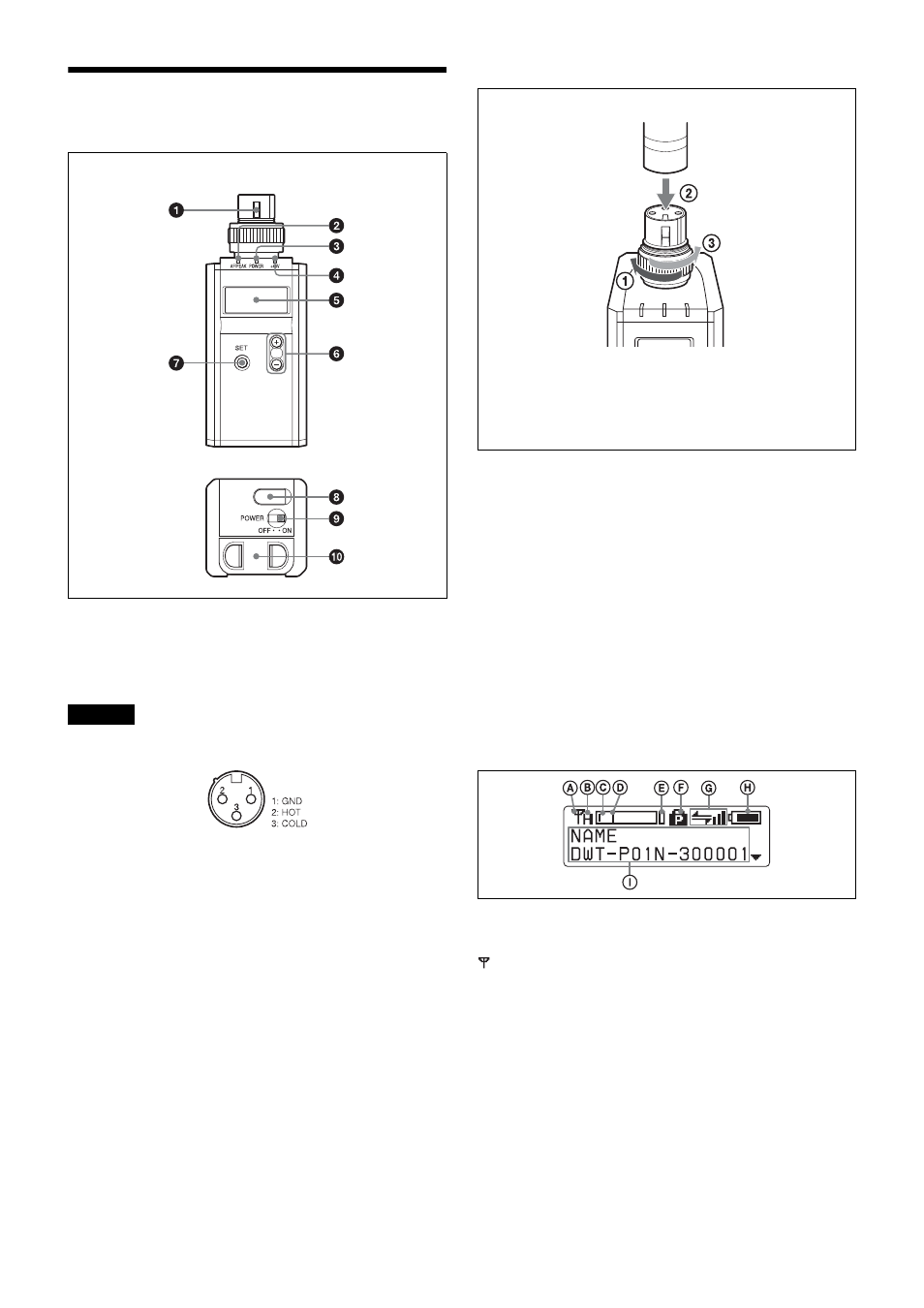
a
Audio input connector (XLR-3-11C)
Connects a microphone with an XLR-3-12C-type output
connector or an audio cable with an XLR-3-12C-type
connector.
Be sure that the transmitter is turned off before connecting
a microphone or cable to the transmitter.
To connect a microphone or a cable
b
AF (audio input level) /PEAK indicator
Lights up green when the signal input is stronger than the
reference level.
Lights up red when the signal input is 3 dB below the level
at which distortion begins.
c
POWER indicator
Lights up green when the transmitter is turned on. When
the battery is exhausted, the indicator starts flashing.
d
+48V indicator
Lights up when INPUT LEVEL is set to MIC and +48 V
power is being supplied to a connected microphone or
other device.
e
Display section
A
RF (radio frequency) transmission indication
Indicates the current transmission status.
:
Currently transmitting
—
:
Transmission stopped
B
RF (radio frequency) transmission power
indication
Indicates the current transmission power setting. You can
change the setting with the RF POWER function.
H:
Transmitting at 50 mW
M:
Transmitting at 10 mW
L:
Transmitting at 1 mW
C
Audio input level meter
Indicates the input signal level.
Caution
Front
Bottom
Microphone or a cable (optional)
Turn the connector ring clockwise (
1
)
and insert the microphone or cable
connector into the audio input connector
until it is fully engaged (
2
). Then turn the
connector ring counterclockwise to
secure the latch (
3
).