Speaker/sound bar on-wall installation, Connecting, Speaker care and cleaning – Klipsch Reference Premiere Designer On-Wall RP-640D 2-Way Speaker (Matte Black, Single) User Manual
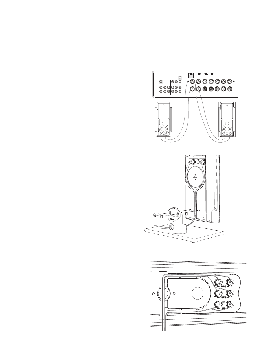
Page 4: Diagram 1 diagram 2 diagram 3
SPEAKER/SOUND BAR ON-WALL INSTALLATION
If you mount your RP-140D,RP-240D,RP-640D speakers or RP-440D sound bar
on a wall, do not attach the pedestals. Determine a suitable location for each
speaker to wall-mount and complete all wiring to all speaker positions before
mounting speakers to the wall.
Do not ceiling-mount
.
1.
If you have the RP-640D or RP-440D
, use included template and choose
mount position for the speaker (horizontal or vertical). Pin template to wall,
making sure it is level (when horizontally mounting) or plumb (when vertically
mounting) and positioned correctly, centered with the TV’s center points for
example. Mark on wall the pilot hole locations through the template and
remove template.
If you have the RP-140D or RP-240D
, mark on wall 2
pilot hole points
9.26”apart for the RP-140D or 13.25”apart for the RP-
240D
(make sure the points are lined up so that the speaker hangs straight
up and down vertically or level horizontally).
For all speakers
, Leave a
minimum of one inch space between speaker cabinet and TV. Keep in mind
that, when mounted, the speaker will “lock” into position 5/16” lower than
where the pilot holes are drilled.
2. Pre-drill pilot holes in marked locations. If drilling into a wall stud (ideal) it is
recommended to use #10 mounting screws
(not included)
to mount the
speaker bracket (RP-640D and RP-440D) or the speaker itself (RP-140D
and RP-240D). If there is no stud where a pilot hole is located, install wall
anchors
(not included)
into the pilot holes to hold the bracket or speaker
instead. Wall anchors should be rated to at least 6 pounds (RP-140D and
RP-240D) or 12 pounds (RP-640D and RP-440D).
3.
If vertical wall-mounting
, feed speaker wire into speaker bottom area
and attach each wire to appropriate screw-terminal binding post (See
Diagram 2).
If horizontal wall-mounting
, feed speaker wire to channel(s)
that start on the back center part of the speaker, then continue running
wire through the channel(s) and attach each wire to the appropriate
screw-terminal binding post the same as if vertical mounting. (See
Diagram 3)
(Note: using speaker wire larger than 18 gauge may
not allow wire(s) to completely fit in channels). If needed, stick the
included adhesive strip on a point over the channel to hold the wires
in place in the channel
. To change the Klipsch logo direction on the
speaker front
gently
pull out one side of it and rotate 45˚.
4. Gently push the speaker onto the two tabs on the mounted bracket through
its keyholes (RP-640D and RP-440D) or onto the two screws in the wall (RP-
140D and RP-240D) and push 5/16” down to lock into position.
CONNECTING
RP-140D, RP-240D, RP-640D Connection - Using 16-gauge or larger speaker
wire, connect the RED “positive” (+) terminal of the LEFT speaker to the RED
“positive” (+) terminal of your amplifier’s LEFT channel. Connect the BLACK
“negative” (-) terminal of the left speaker to the BLACK “negative” (-) terminal of
your amplifier’s left channel. Repeat this procedure for connecting all remaining
speakers to the appropriate amplifier channels.
RP-440D sound bar Connection - Since this speaker contains the LEFT, RIGHT
and CENTER channels, connect each one of these channels from your amplifier
as above to the designated “Left”, “Right” and “Center” terminals on the RP-
440D.
Make sure that no bare wires from any of the connections touch each other or
any other terminals as this could cause a short and damage your equipment.
SPEAKER CARE AND CLEANING
Your Klipsch Reference Premiere Designer On-Wall Speaker has a durable finish
that should only require dry dusting or cleaning with a dry cloth. Avoid the use
of abrasive or solvent-based cleaners and harsh detergents. The unique grille
for the speaker consists of a piece of sheer rectangular cloth with metal rods
along two sides. It is held in place by magnets embedded in a slot on each
side of the rear of the cabinet. Carefully pull the metal rod away from one side,
then the other to remove grille. The grille is designed to be as lightweight and
acoustically transparent as possible so there is no rigid framework behind it.
Because of this, it might be necessary to “smooth” the cloth once the grille is
attached to the cabinet by using two thumbs to pull the cloth taught from top to
bottom (or side to side if unit is mounted horizontally).
DIAGRAM 1
DIAGRAM 2
DIAGRAM 3
Front Left
Front Right
Back Surround
Left
Back Surround
Right
Surround
Right
Surround
Left
Speaker Hookup
Center
HDMI Out
HDMI 1
HDMI 2
HDMI 3
L
R
L
R
CD
TAPE
TV
DVD
Monitor
Out
Video
In
Out
In
In
In
In
CBL/SAT
Sub Pre Out