Whirlwind MCT7 - Multi Connector Cable Tester User Manual
Page 2
commencing testing, you check battery status (See section “
Testing and Replacing
Battery
“).
TEST PROCEDURE:
The MCT-7 Cable Tester is simple to operate. A schematic diagram of the
connectors and their pin assignments is shown on the front panel of the unit. Light
Emitting Diodes (LEDs) give a clear visual representation of the connections.
YELLOW LEDs 1-5 refer to the pins of connectors on the left side (INPUT) of the
unit. Green LEDs 1-5 refer to the pins of connectors on the right side (OUTPUT) of the
unit.
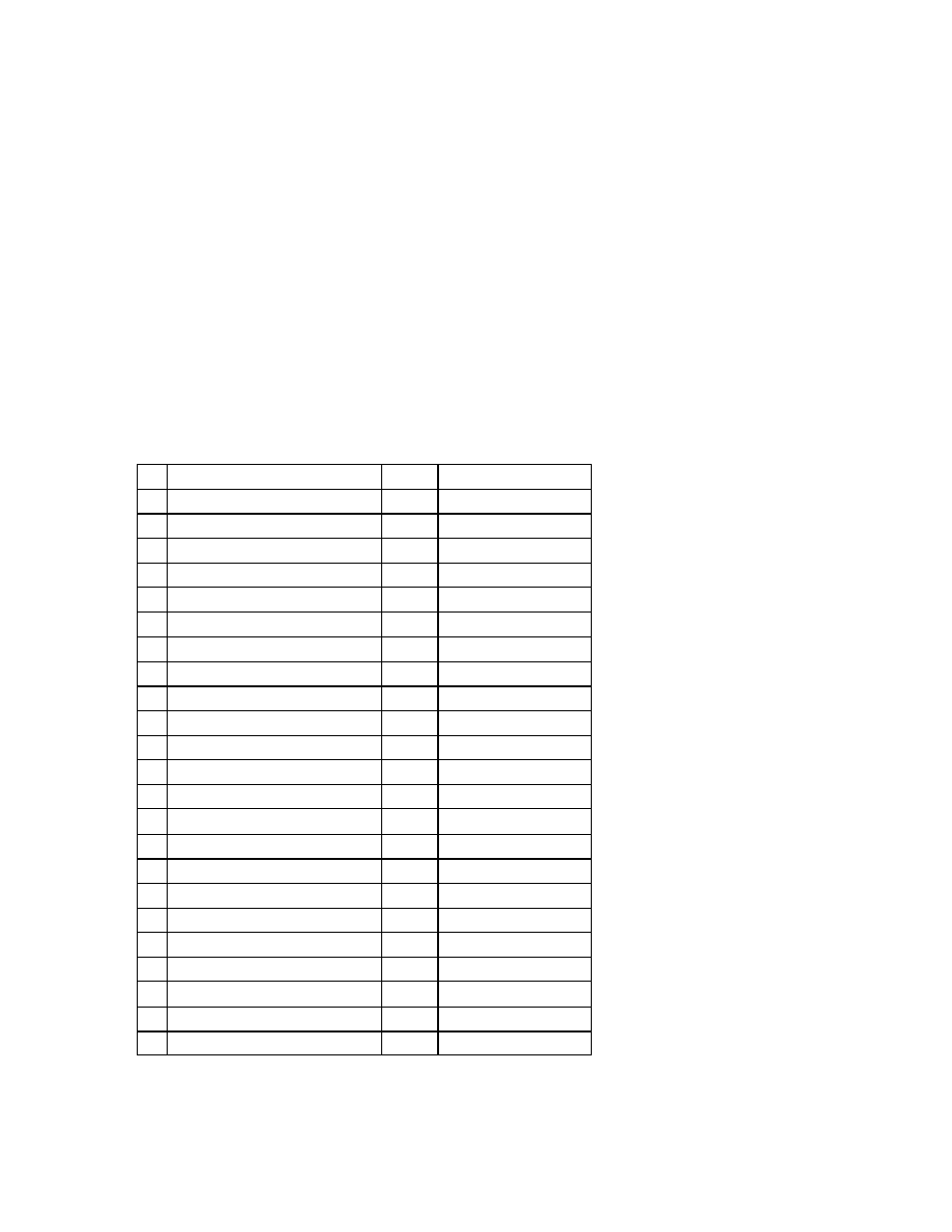
Checking the status of connections is made using the Pin Selector Switch. Until
you become familiar with the connectors, pin wiring and switch selector positions, you
may wish to refer to the data shown in Table 1.
Table 1
Connector
Pin
Assigned Position
A
Speakon NL4
1
2
-1
1
2
4
-2
3
B
Phono/RCA
Center
2
Ring
1
B
BNC / Video
Center
2
Ring
1
C
MIDI 5 DIN
1
1
2
2
3
3
4
4
5
5
D
Jack 3.5mm (1/8”)
Tip
2
Ring
3
Sleeve
1
D
Jack 6.3mm (1/4”)
Tip
2
Ring
3
Sleeve
1
E
Male or female XLR
1
1
2
2
3
3
1. Plug one end of the lead to be tested into the corresponding connector on the
INPUT (left) side of the unit.