2 connect the beeper and led – GeoVision GV-R1352 Card Reader (13.56 MHz) User Manual
Page 37
28
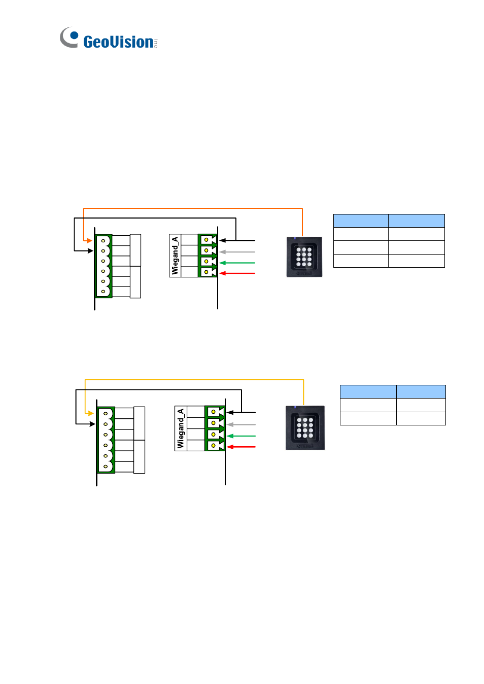
2.6.2 Connect the Beeper and LED
Connect the control wires of the beeper, Red LED, or Green LED to any of the outputs on the
GV-AS Controller (GV-AS210 / 2110 / 2120 / 410 / 4110 / 810 / 8110).
Wiring LED to GV-AS Controller
The diagram below shows how to wire Green LED using GV-RK1352 and GV-AS810 as an
example. Use the light red wire instead for Red LED.
GV-AS810 Controller
GV-RK1352
or GV-R1352
O
U
T
11
O
U
T
12
NC
COM
NO
NC
COM
NO
Green LED (Orange)
12V
D0
D1
GND
(Black)
(Green)
(White)
(Red)
Wire Color
Function
Black
GND
Orange
Green LED
Light Red
Red LED
Wiring Beeper to GV-AS Controller
The diagram below shows how to wire the beeper using GV-RK1352 and GV-AS810 as an
example.
GV-AS810 Controller
O
U
T
11
O
U
T
12
NC
COM
NO
NC
COM
NO
Beeper (Yellow)
12V
D0
D1
GND
(Black)
(Green)
(White)
(Red)
GV-RK1352
or GV-R1352
Wire Color
Function
Black
GND
Yellow
Beeper