Setup, Dante controller, Technical specification – Sonifex AVN-DIO08 Dante to AES3 Terminal Block Stereo Input & Output Converter User Manual
Page 2
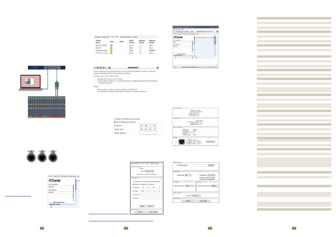
Network Troubleshooting
The device can be seen within Dante® Controller if it is connected to the same
network as the computer. If the device doesn’t show up in Dante® Controller
please check that the connec�on to the network is correct and that the device
and computer are on the same network.
If the computer and the device are on different IP subnets, the device will
appear in Dante® Controller with red text:
Fig 1-4: Red Device Name Indicates Different Network Subnet
Opening the
Device View
for the device will provide details about the problem.
Fig 1-5: Problem Details
In this example no�ce the device is on the 192.168.1.X subnet and the
computer is on the 10.X.X.X subnet. To correct this, edit the computer’s IP
address.
In Windows 10, type
View Network Connec�ons
into the search bar. Right-click
the network that the device is connected to and select
Proper�es.
Double click
Internet Protocol
Version 4 (TCP/IPv4)
in the item list and
edit the IP address.
Fig 1-6: Windows IPv4
Se�ngs
Save the changes made to the se�ngs then close and re-open Dante®
Controller. The device should now appear correctly. If the device name is s�ll
red, you may need to disable the other network connec�ons on the computer.
To do this, in Windows 10, type
View Network Connec�ons
into the search bar.
Right-click the network connec�on to disable and select
Disable
.
Now that the device appears in Dante® Controller, it can be configured and the
network se�ngs can be modified so that the device is in the correct subnet.
Open the
Device View
for the device and
select the
Network Config
tab. Within this
tab are op�ons to obtain an IP address
automa�cally, or to configure an IP
address manually.
A�er configuring the devices address, click
the
Reboot
bu�on and then revert your
computers IP address so that it is on the
original subnet using the process above.
Fig 1-7: Dante Controller Network Config
For more troubleshoo�ng informa�on
please see the official Dante® FAQs at:
Setup
The DIO Dante device is configured with a dynamic network address, so to
ini�ally get the unit working, connect it to a network with a DHCP server (such
as a router) and a suitable IP address will be given to the unit. Once connected,
a different IP address can be given to the DIO using Dante Controller. See the
following sec�on on Network Troubleshoo�ng if you’re having problems
connec�ng your DIO device.
Simply plug an Ethernet connector into the Ethernet port of the DIO and the
other end of the Ethernet connector into a PoE enabled switch. Alterna�vely, if
the switch doesn’t support PoE, a PoE adaptor can be used to provide the
power.
The audio inputs/outputs should be connected to the legacy equipment and this
allows the legacy equipment to transmit audio and receive audio through the
Dante® network.
A computer on the Dante® network can then configure connec�ons between
the DIO and other Dante® enabled devices, using Dante Controller.
Fig 1-1: Setup
Link
Link status is indicated using the top-le� status LED. Once power has been
supplied to the unit the link status LED turns red. The link status LED turns
amber when a link is established with a link speed of 100 Mbps.
Link ac�vity is indicated using the top-right status LED which blinks when data is
incoming, or when outgoing data is sensed on the port.
Fig 1-2: Power, Link, and Ac�vity LEDs
Dante Controller
Once a link has been established Dante
Controller can be used to configure the
device. Dante Controller is an applica�on
provided by Audinate and can be
downloaded from their website.
Within Dante Controller the unit should be
visible within the
Rou�ng
tab.
Fig 1-3: Rou�ng
PC Running
Dante
Controller
Analogue/Digital
Legacy
Equipment
Network
Switch
AVN-DIO
Audio
Network
5
6
7
8
Technical Specification
Routing Audio
Audio can be routed seamlessly between each Dante® enabled device on the
network by crea�ng connec�ons between the transmit channel of one device
and the receive channel of another device. When a rou�ng is ini�ally created,
an hour glass is displayed to
show the connec�on is being
created. A�er a short �me a
green �ck is displayed to
indicate the connec�on has
been created successfully.
Transmi�ers and receivers
can also be filtered by typing
a name into the
corresponding filter field.
Further filtering op�ons are
available from the filter
pane.
Fig 1-8: Routed Audio Stream
To remove a connec�on simply click on the green �ck.
Transmit and receive channels in a diagonal can be quickly routed together by
holding
Ctrl
and clicking on the minimise/maximise bu�on on the rou�ng grid.
Device View
Open up the
Device View
by double clicking on the device name in the rou�ng
grid.
Status
Within the
Status
tab, informa�on about the device can be seen, such as the
product type and the current IP address.
Fig 1-9: Status
Device Configuration
Within the
Device Config
tab the following can be modified.
•
Device Name
•
Sample Rate
•
Encoding
•
Clocking
•
Device Latency
An op�on is also available to
clear the configura�on,
rese�ng all se�ngs to their
default values.
Fig 1-10: Device Config
▲
AES3 XLR Stereo Input Pin-out
Pin
Func�on
1
Chassis Ground
2
Input Phase
3
Input Non Phase
AES3 XLR Stereo Output Pin-out
Pin
Func�on
1
Chassis Ground
2
Output Phase
3
Output Non Phase
AES3 BNC Input & Output Pin-out
Pin
Func�on
Inner Signal
Outer Chassis Ground
AES3 Terminal Stereo Input & Output Pin-out
Pin
Func�on
Pin
Func�on
1
Chassis Ground
4
Chassis Ground
2
Input Phase
5
Output Phase
3
Input Non Phase
6
Output Non Phase
Power Supply - Class 0 802.3af PoE
Device
Power Consump�on (Wa�s)
DIO06, DIO07, DIO08
< 3 W
AES3 Input - XLR/Terminal
Parameter
Descrip�on
Input Impedance
110Ω balanced
Input Format
AES-3
Supported Sample Rates
32kHz, 44.1kHz, 48kHz, 88.2kHz, 96kHz,
176.4kHz, 192kHz
AES3id Input - BNC
Parameter
Descrip�on
Input Impedance
75Ω unbalanced
Input Format
AES-3id
Supported Sample Rates
32kHz, 44.1kHz, 48kHz, 88.2kHz, 96kHz,
176.4kHz, 192kHz
AES3 Output - XLR/Terminal
Parameter
Descrip�on
Output Impedance
110Ω balanced
Output Format
AES-3
Supported Sample Rates
44.1kHz, 48kHz, 88.2kHz, 96kHz
AES3id Output - BNC
Parameter
Descrip�on
Output Impedance
75Ω unbalanced
Output Format
AES-3id
Supported Sample Rates
44.1kHz, 48kHz, 88.2kHz, 96kHz
Dante
Parameter
Descrip�on
Sample Rates:
44.1kHz, 48kHz, 88.2kHz, 96kHz
Encoding:
PCM 16, PCM 24, PCM 32
PoE Power
Standard:
802.3af
Class:
0
PD Power Range:
0.44 W to 12.94 W
Typical PSE Power Usage:
AVN-DIO06
2W
AVN-DIO07
2W
AVN-DIO08
2W
Max PSE Power Usage:
15.4 W
Equipment Type
AVN-DIO06
Dante® to AES3 XLR Stereo Input & Output
AVN-DIO07
Dante® to AES3 BNC Stereo Input & Output
AVN-DIO08
Dante® to AES3 Terminal Block Stereo Input &
Output
Physical Specifica�on
AVN-DIO06
Dimensions (Raw):
10.6cm (W) x 7.3cm (D) x 4.3cm (H)
4.2” (W) x 2.9” (D) x 1.7” (H)
AVN-DIO07
Dimensions (Raw):
11.6cm (W) x 7.3cm (D) x 4.3cm (H)
4.6” (W) x 2.9” (D) x 1.7” (H)
AVN-DIO08
Dimensions (Raw):
10.6cm (W) x 7.3cm (D) x 4.3cm (H)
4.2” (W) x 2.9” (D) x 1.7” (H)
AVN-DIO06,07,08
Dimensions (Boxed):
17.4cm (W) x 9.5cm (D) x 5.6cm (H)
6.9” (W) x 3.7” (D) x 2.2” (H)
Weight
AVN-DIO06,07,08
Weight:
Ne�: 0.2kg Gross: 0.3kg
Ne�: 0.44lbs Gross: 0.66lbs
Powered
Powered
with link
Powered
with ac�vity