Steelcraft products, Model, Sheet 1 1 4 – LA STEELCRAFT 810KD User Manual
Page 3
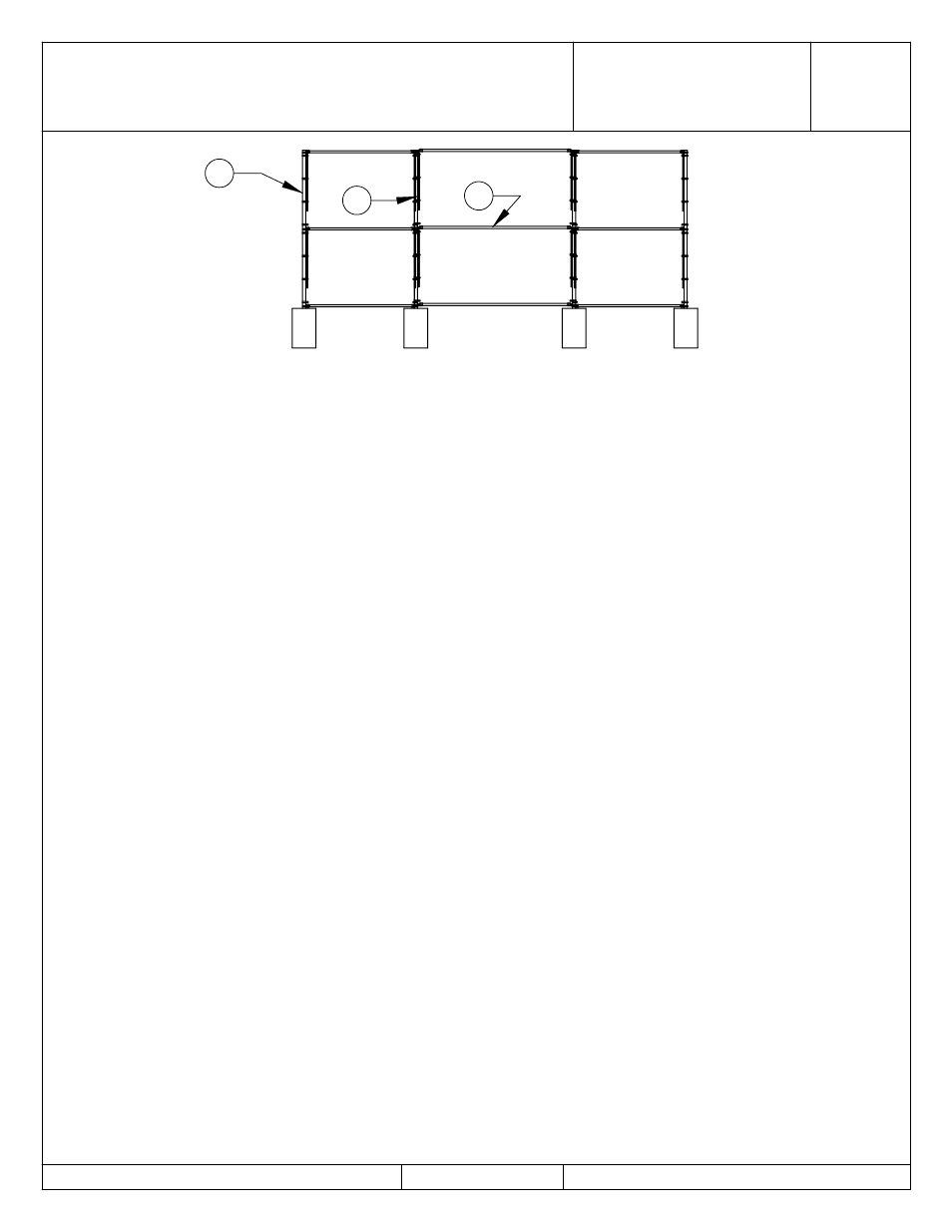
BACKSTOP
810 KD
BASEBALL
3 OF 3
DO NOT SCALE DRAWING
STEELCRAFT PRODUCTS
PHN 626-798-7401 FAX 626-798-1482
MODEL
DATE: 2/6/12
DRAWN BY: AFS
P.O. Box 90365 - Pasadena, CA 91109
SHEET
1
1
4
ASSEMBLY INSTRUCTIONS
1.
Dig four (4) holes @ 30" deep and 18" dia. as shown on the plan view.
2.
Place two 2-3/8" od back posts “1” in the back holes.
3.
Place two 2-3/8" od end posts “1” in the front holes.
4.
Each post shall be 10'-0" above ground and 10'-0" on center. Place a horizontal brace “4”
on the ground between each of the posts. Place a rail end fitting on each end of these
braces. Place a brace band over each post adjacent to each rail end fitting. Bolt rail
end fitting to the corresponding brace band. Make sure the horizontal brace fits into the rail
end fittings at least 1". If they don't, adjust the posts accordingly.
**NOTE: All carriage bolt heads are facing the playing field.
5.
With the proper spacing assured, plumb all posts and pour the concrete footings. Allow
24 hrs. for concrete to set and then proceed as follows.
6.
Install horizontal braces “4” between the posts above ground. These braces can be
installed in a manner similar to directions in item 4.
7.
Unroll the 9 ga. wire from end of roll. Stretch the wire for measuring and open the
knuckle on each side of the roll at 9'-7" and weave out one strand of wire.
8.
Weave a tension bar through the last loops and place this wire against playing field side of one of
the wing panels with the tension bars parallel to the uprights.
9.
Stretch wire on the wing panels. Slip 6 tension bands over each post adjacent to the
tension bars. The tension bars must be offset so that the wire will be stretched on the
playing field side (inside) of the backstop. Equally space the 6 tension band up and down
the posts on each side of the wire panel and bolt into position.
**NOTE: If the wire is too loose, remove a strand of wire as in item 7 above or,
if the wire is too tight to fasten into position, reweave into panel, the strand of
wire removed in item 7 above.
10.
Stretch Wire Back Panel The back panel will be stretched in one piece between
outside back posts “1”. The length of the wire needed should be 3" shorter than the
distance between the inside of the two posts. (Make sure wire is stretched when
measuring)
11.
Place this wire against the playing field side of the backstop with the tension bars
parallel and adjacent to posts “1”. Stretch and secure into position with 6 tension bands
on each post.
12.
Install and stretch wire in the opposite wing as described in items 8 and 9 above.
13.
Use tie wire and tie all chain link to the adjacent horizontal braces at approx. 18" apart.
14.
Tighten all set screws and bolts & nuts.