Nexen 625 Puck Caliper 837100 User Manual
Page 6
Advertising
6
FORM NO. L-20118-C-1209
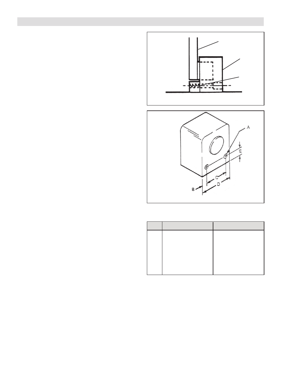
FIGURE 1
INSTALLATION
1. Provide a flat mounting surface below the rotor disc
(See Figure 1).
2. Drill and tap mounting surface. See Figure 2 and
Table 1 for hole locations.
3. Using socket head cap screws (#10-24 for Model
625 and 1/4-20 for Model 1000) mount brake (See
Figure 1).
NOTE: Allow .030 clearance between Rotor Disc
and Brake Housing (See Figure 2)
4. Tighten cap screws to 5 ft/lbs torque for Model 625
and 9 ft/lbs torque for Model 1000.
Rotor Disc
Brake
Mounting
Surfaces
FIGURE 2
TABLE 1
Dim.
625
1000
A
7/32 in [5.57 mm]
9/32 in [7.41 mm]
B
5/16 in [7.94 mm]
1/4 in [6.35 mm]
C
5/8 in [15.87 mm]
1-1/8 in [28.57 mm]
D
1-1 /4 in [31.75 mm] 1-5/8 in [41.27 mm]
E
5/16 in [7.94 mm]
.3/8 in [9.52 mm]
Advertising
This manual is related to the following products: