Nexen 8K 845200 User Manual
Page 8
5
FORM NO. L-20013-K-0210
PARTS REPLACEMENT
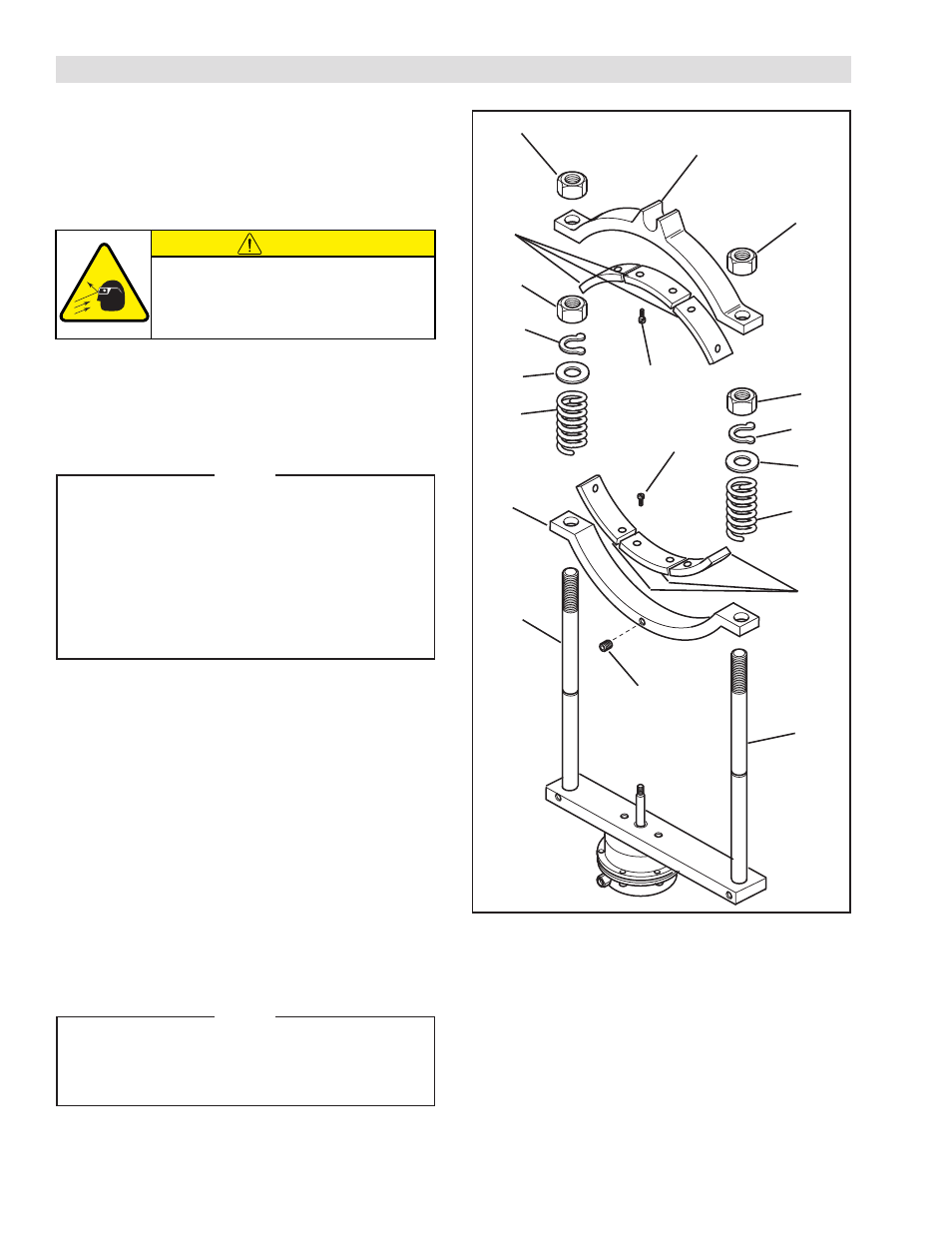
FRICTION FACINGS
REFER TO FIGURE 4.
1. Remove two Jam Nuts (Item 12) and slide the Fixed
Shoe (Item 1) off the Guide Rods (Item 21); then,
remove the second two Jam Nuts (Item 12.
CAUTION
Working with spring loaded or tension
loaded fasteners and devices can cause
injury. Wear safety glasses and take the
appropriate safety precautions.
2. Remove two Retaining Rings (Item 24), Washers
(Item 23), and Guide Rod Springs (Item 22).
3. Remove the Set Screw (Item 13); then, slide the
Sliding Shoe (Item 2) off the Guide Rods (Item 21).
NOTE
The Flat Head Machine Screws (Item 20) are
assembled with an anaerobic locking compound.
Inserting a properly fitting screwdriver into the
head of the Flat Head Machine Screw and
striking the end of the screwdriver with a
hammer will break the crystalline structure of
the locking compound and allow removal of the
Flat Head Machine Screw. Never use an impact
wrench to remove the Flat Head Machine Screws.
4. Remove the Flat Head Machine Screws (Item 20)
from the Fixed Shoe (Item 1) and the Sliding Shoe
(Item 2); then, remove the Friction Facings (Item 3)
from the Fixed Shoe and Sliding Shoe.
5. Using new Flat Head Machine Screws (Item 20),
secure the new Friction Facings (Item 3) to the Fixed
Shoe (Item 1) and the Sliding Shoe (Item 2).
6. Tighten the Flat Head Machine Screws (Item 20) to
26 in-lbs [2.9 Nm] torque.
7. Slide the Sliding Shoe (Item 2) back onto the Guide
Rods (Item 21).
8. Reinstall and tighten the Set Screw (Item 13) to
80 in-lbs [9.0 Nm] torque.
NOTE
Inspect the Guide Rod Springs (Item 22) for
signs of fatigue or cracking. If the Guide Rod
Springs show signs of fatigue or cracking they
must be replaced.
9. Reinstall the Guide Rod Springs (Item 22), Washers
(Item 23), and Retaining Rings (Item 24) onto the
Guide Rods (Item 21).
10. Install a Jam Nut (Item 12) onto each Guide Rod
(Item 21); then, slide the Fixed Shoe (Item 1) onto
the Guide Rods and install the remaining two Jam
Nuts (Item 12) securing the Fixed Shoe to the Guide
Rods.
12
12
12
12
1
24
24
23
23
22
22
2
21
21
13
20
20
3
3
FIGURE 4