Installation – Nexen EMB-1125 965300 User Manual
Page 5
5
FORM NO. L-21068-G-0711
INSTALLATION
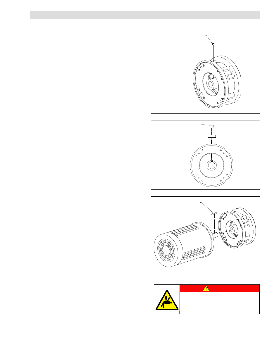
FIGURE 2
FIGURE 1
FIGURE 3
NOTE: Before beginning any assembly, check the position
of the Set Screw (Item 7) in the Output Shaft (Item 1). It
is important that the bottom be high enough to allow the
installation of the supplied key (Item 12). Interference
between the set screw and key could cause damage and
will not allow full motor shaft insertion.
1. Remove one of the Access Plugs (Item 14) from the Input
Flange (Item 10). Insert an Allen Driver or T-Handle wrench
through the access hole, and engage the head of the set
screw.
NOTE: Nexen has designed the Input Flange (Item 10)
with two access holes, 180
°
apart from each other. Only
one hole is needed for access to the set screw. This
design allows for ease of access in tight applications and
shorter shaft rotations if a problem arises. Only one plug
must be removed to have access to the set screw.
2. Install the supplied Key (Item 12) into the slot on the Motor
Shaft. A small amount of grease can aid in the securing of
the Key while installing the Brake.
3. Slide the Motor Shaft into the input (female) end of the
Output Shaft (Item 1) until the Flanges of the Motor and
Brake come together.
4. Using four customer supplied Socket Head Cap Screws
(½ -13 UNC), bolt the Flanges together. Tighten the Cap
Screws evenly to the recommended torque (1400 in-lb).
5. Using the allen driver or wrench used in step 2, tighten the
Set Screw (Item 7) to the recommended torque (100 in-
lb).
6. Reinstall the Access Plug (Item 14) in the access hole in
the Input Flange (Item 10).
7. Assemble the Gear Reducer or load to the output end of
the Brake Shaft.
INSTALLATION ONTO MOTOR SHAFT
KEY
(ITEM 12)
5/16-24 UNF SET SCREW
(ITEM 7)
ACCESS PLUG
(ITEM 14)
DANGER
Support the load before disengaging
the brake. Failure to support the load
could result in serious bodily injury.