Nexen MB600 801305 User Manual
Page 9
6
FORM NO. L-20124-G-0210
CAUTION
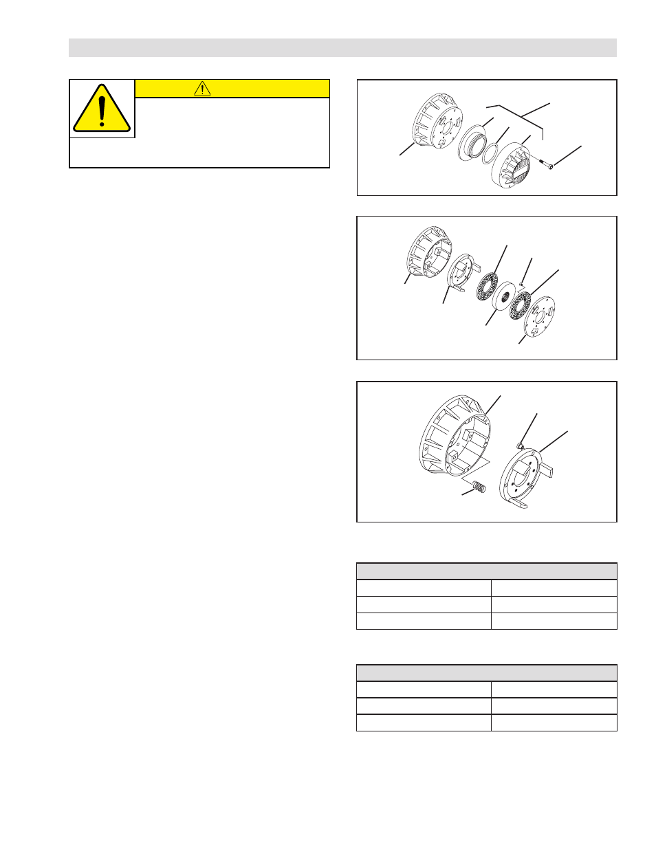
PARTS REPLACEMENT
FIGURE 6
FIGURE 7
REFER TO FIGURES 5-7.
1. Alternately and evenly remove the six Socket Head
Cap Screws (Item 12).
2. Remove the Cylinder Assembly and separate the
Piston (Item 5) from the Cylinder (Item 6).
3. Remove the old O-ring Seal (Item 9) and clean the
O-ring seal contact surfaces with fresh safety
solvent.
4. Lubricate the new O-ring Seal (Item 9) with fresh O-
ring lubricant and install the new O-Ring Seal onto
the Piston (Item 5).
5. Slide the Piston (Item 5) and O-Ring Seal (Item 9
into the Cylinder (Item 6).
6. Slide the Pressure Plate (Item 4), Drive Disc (Item 3),
and Torque Plate (Item 2) out of Housing (Item 1).
7. Remove the twelve old Machine Screws (Item 8
securing the old Friction Facings (Item 7) to the
Torque Plate (Item 2) and the Pressure Plate (Item 4).
8. Using twelve new Machine Screws (Item 8), secure
the new Friction Facings (Item 7) to the Torque Plate
(Item 2) and the Pressure Plate (Item 4).
9. Tighten the twelve Machine Screws (Item 8) to the
recommended torque (See Table 4).
10. Remove old Sleeve Bearings (Item 11) and install
new Sleeve Bearings provided in repair kit.
11. Inspect the Compression Springs (Item 14) for signs
of wear or fatigue and replace them if necessary.
12. Slide the Pressure Plate (Item 4), Drive Disc (Item 3),
and Torque Plate (Item 2) into the Housing (Item 1).
13. Apply a drop of Loctite
®
242 to the six Socket Head
Cap Screws (Item 12) and secure the Piston (Item 5)
and Cylinder (Item 6) to the Housing (Item 1).
14. Alternately and evenly tighten the six Socket Head
Cap Screws (Item 12) to the recommended torque
(See Table 5).
FIGURE 5
Nexen MB Series Motor Brakes are spring
engaged. The Compression Springs (Item
14) may force the Cylinder Assembly off
the Housing resulting in operator injury. Use caution when
removing the Socket Head Cap Screws.
12
Cylinder
Assembly
6
5
9
Housing
4
3
2
1
7
8
7
2
1
14
11
TABLE 4 Recommended Tightening Torque
TABLE 5 Recommended Tightening Torque
Machine Screw (Item 8)
MB450S
14 in-lbs [1.58 Nm]
MB600S
14 in-lbs [1.58 Nm]
MB800S
46 in-lbs [5.19 Nm]
Socket Head Cap Screw (Item 17)
MB450S
14 in-lbs [1.58 Nm]
MB600S
46 in-lbs [5.19 Nm]
MB800S
80 in-lbs [9.03 Nm]