Nexen LSCB-32 923522 User Manual
Page 10
10
FORM NO. L-21143-J-0413
REPAIR KIT
The repair kit replaces bearings, o-rings, friction facings,
friction plates, and springs.
NOTE: The following tools are needed to press the unit
apart: a shaft, two sections of I-beam, and standard
retaining ring pliers.
To press the unit together, use a hollow shaft fixture,
making sure there is contact with the inner race of the
bearing while pressing (See Table 3 & Figure 3).
1. Remove the three Set Screws (Item 16) from the Hub
(Item 1).
2. Remove the Retaining Ring (Item 14) from the Hub
(Item 2) at the Pilot end of the unit.
3. Fasten a sprocket or a pair of plates to the Pilot
mounting holes (See Table 1).
4. Set the sprocket on the two pieces of I-beam (as shown
in Figure 2) with the pilot end of the unit resting on the
I-beams.
NOTE: Support the Air Chamber end of the unit as the
Hub is pressed out to prevent the unit from falling to
the floor. Nexen also recommends placing the assembly
in a box or bag to avoid loss of any small components
(i.e. springs).
5. Using an Arbor Press, align the proper diameter shaft
with the Hub (Item 1) and apply pressure with the Arbor
Press to separate the Pilot assembly from the Hub (Item
1) (See Table 3).
6. Remove Friction Facings (Item 4) and Friction Plates
(Item 5) along with the springs from the drive pins.
7. Remove the Retaining Ring (Item 14) from the Air
Chamber (Item 3).
HT Models only: Remove the shoulder bolts and springs
(Item 22) from the Air Chamber (Item 3).
8. Flip unit over (Hub facing down) and rest the edges
of the Air Chamber (Item 3) on I-beam and press the
Hub-Piston assembly from the Air Chamber.
LSCB-54HT only: Remove the Retaining Ring (Item 25)
that secures the brake facing in the piston. The worn
facing can then be removed.
LSCB-44HT only: While supporting the piston assembly,
drive the splines of the hub through the conical Friction
Facing (this will destroy the facing) (Item 20).
LSCB-32HT only: Remove Bearing (Item 10) from Thrust
Plate (Item 26). Remove pan head screw (Item 8) from
the piston assembly. Discard the damaged Bearing
(Item 10). [Note: Skip step 10]
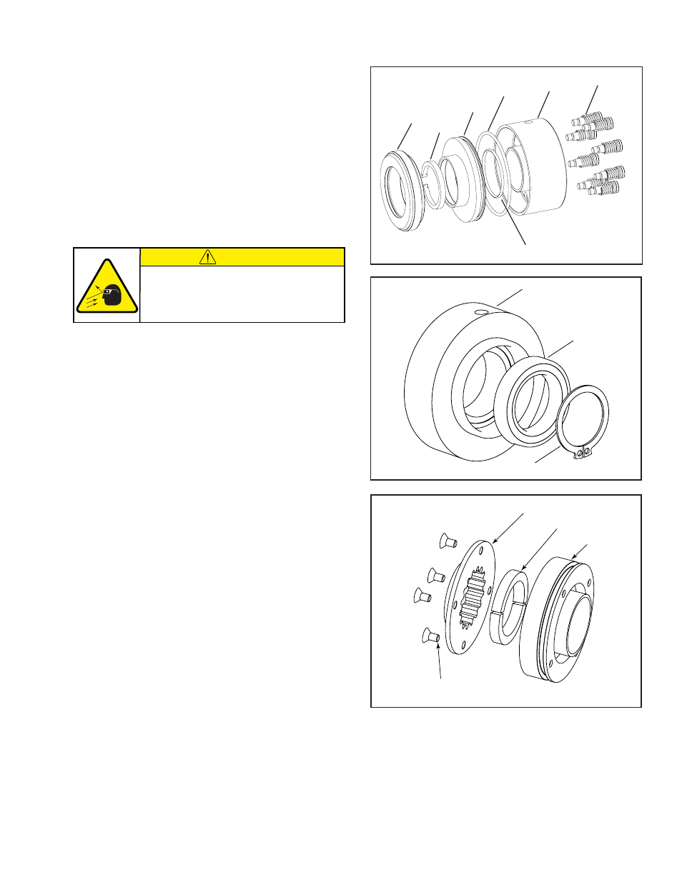
Figure 4
12
13
10
11
3
20
21 & 22
Figure 5
3
6
14
8
11
20
26
Figure 6
MAINTENANCE (continued)
9. Remove discard the worn conical Friction Facing (Item
20).
Refer to Figures 3 & 4.
10. Remove Bearing (Item 10) from the Piston (Item 11).
11. Clean the new Bearing (Item 10) and Piston (Item 11)
surfaces.
CAUTION
Working with spring loaded or tension
loaded fasteners and devices can cause
injury. Wear safety glasses and take the
appropriate safety precautions.
- LSCB-54HT 923627 LSCB-54HT 923625 LSCB-54HT 923624 LSCB-54HT 923591 LSCB-44 923570 LSCB-32HT 923520 LSCB-44HT 923596 LSCB-44HT 923597 LSCB-44HT 923579 LSCB-44HT 923623 LSCB-44HT 923589 LSCB-44HT 923584 LSCB-44HT 923571 LSCB-44HT 923634 LSCB-44HT 923609 LSCB-44HT 923629 LSCB-44HT 923608 LSCB-32 923521 LSCB-44 923572 LSCB-44 923573 LSCB-44HT 923574 LSCB-44 923575 LSCB-54HT 923592 LSCB-54 923593