Nexen MCB-800 830853 User Manual
Page 9
FORM NO. L-21082-E-0110
9
PARTS REPLACEMENT
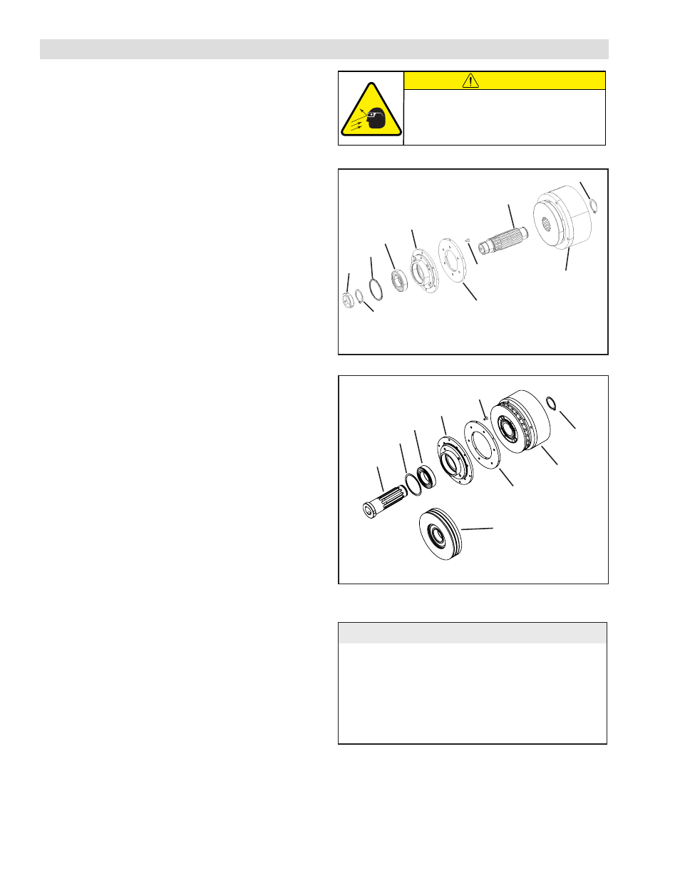
NOTE: Refer to Figures 5 and 6 for steps 1-13.
1. Remove the Retaining Ring (Item 11) and press the Air
Chamber Assembly off the Hub (Item 1).
NOTE: Step two refers only to FCB-450 models; for all
other models, go directly to step three.
2. Remove the Set Screws (Item 20), Hub Collar (Item
25), and Retaining Ring (Item 11b) from the Hub (Item
1).
3. Press the Pilot Mount Drive Disc (Item 7) or Sheave
(Item 30) off the Hub (Item 1).
4. Remove the Retaining Ring (Item 15) from the Pilot
Mount Drive Disc (Item 7) or Sheave (Item 30).
5. Press the old Ball Bearing (Item 8) out of the Pilot Mount
Drive Disc (Item 7) or Sheave (Item 30).
6. Clean the bearing bore of the Pilot Mount Drive Disc
(Item 7) or Sheave (Item 30) with fresh safety solvent,
making sure all old Loctite
®
(or
equivalent
) residue is
removed.
7. Apply an adequate amount of Loctite
®
680 (or
equivalent
) to evenly coat the outer race of the new Ball
Bearing (Item 8).
8. Supporting the Pilot Mount Drive Disc (Item 7) or the
Sheave (Item 30) and pressing on the outer race of the
new Ball Bearing (Item 8), press the new Ball Bearing
into the Pilot Mount Drive Disc or Sheave.
9. Reinstall the Retaining Ring (Item 15) into the Pilot
Mount Drive Disc (Item 7) or Sheave (Item 30).
10. Remove the six Flat Head Screws (Item 24) and the
old Friction Facing (Item 23) from the Pilot Mount Drive
Disc (Item 7) or Sheave (Item 30).
11. Using six new Flat Head Screws (Item 24), secure the
new Friction Facing (Item 23) to the Pilot Mount Drive
Disc (Item 7) or Sheave (Item 30).
12. Alternately and evenly tighten the six flat head screws
(Item 24) to the recommended torque. (See Table 3.)
13. Supporting the inner race of the new ball bearing, press
the new Ball Bearing (Item 8) and Pilot Mount Drive
Disc (Item 7) or Sheave (Item 30) onto the Hub (Item
1).
(continued...)
l
e
d
o
M
.
o
N
m
e
t
I
n
o
i
t
p
i
r
c
s
e
D
e
u
q
r
o
T
0
5
4
-
B
C
F
4
2
w
e
r
c
S
d
a
e
H
t
a
l
F
s
b
l-
n
i
2
2
-
6
1
]
m
N
5
.
2
-
8
.
1
[
0
0
6
-
B
C
L
4
2
w
e
r
c
S
d
a
e
H
t
a
l
F
b
l-
n
i
2
2
-
6
1
]
m
N
5
.
2
-
8
.
1
[
0
0
8
-
B
C
M
4
2
w
e
r
c
S
d
a
e
H
t
a
l
F
b
l-
n
i
1
8
-
2
6
]
m
N
2
.
9
-
0
.
7
[
TABLE 3
11
Air Chamber
Assembly
23
25
7
8
15
1
24
11b
FIGURE 5
FCB-450 Exploded Diagram
FIGURE 6
11
Air Chamber
Assembly
23
30
24
7
8
15
1
LCB-600 & MCB-800 Exploded Diagram
CAUTION
Working with spring loaded or tension
loaded fasteners and devices can cause
injury. Wear safety glasses and take the
appropriate safety precautions.