Nexen FMCBES-625 801652 User Manual
Page 12
FORM NO. L-20178-N-0513
12
NOTE
Remove the Plug (Item 27) and loosen the Set
Screw (Item 26) one full turn to release the Input
Unit from the FMCBES. Both the Plug (Item 27) and
Set Screw (Item 26) are located on the FMCBES
Housing.
1. Remove the socket head cap screws and Hex. head
nuts securing the Input Unit to the FMCBES; then,
remove the Input Unit from the FMCBES.
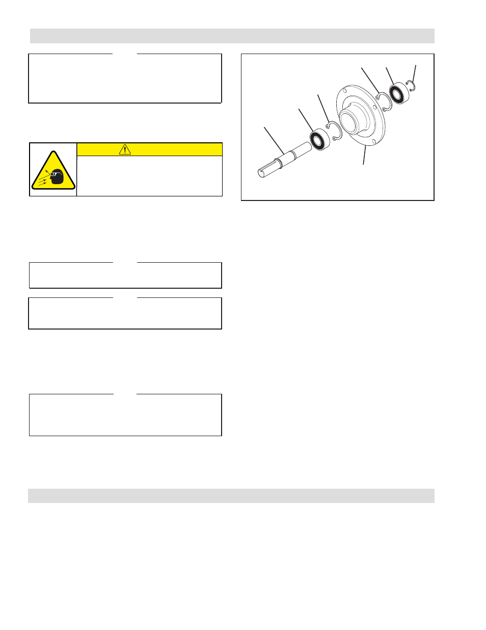
2. Remove the Retaining Ring (Item 35) from the output
end of the Input Unit (See Figure 11).
3. Fully supporting the Flange (Item 20), press the Shaft
(Item 11) out of the Input Unit (See Figure 11).
NOTE
It is not necessary to remove the retaining rings
from the inside of the flange.
NOTE
One Bearing (Item 30) will come out of the Flange
(Item 20) with the Shaft (Item 11) (See Figure 11).
4. Press the old Bearing (Item 30) out of the Flange
(Item 20) (See Figure 11).
5. Press the old Bearing (Item 30) off the Shaft (Item 11)
(See Figure 11).
NOTE
Do not reuse the old Bearings (Item 30). Applying
force to the inner race of a bearing to remove a
bearing held by the outer race causes damage to
the bearing.
6. Clean the bearing bore of the Flange (Item 20) with
fresh safety solvent, making sure all old Loctite
®
residue
is removed.
7. Press one new Bearing (Item 30) onto the Shaft
(Item 11) until it is seated against the retaining ring on
the Shaft (See Figure 11).
8. Apply an adequate amount of Loctite
®
680 to evenly
coat the outer race of the second new Bearing (Item
30) (See Figure 11).
9. Carefully align the outer race of this new bearing with
the bore of the Flange (Item 20) and press this Bearing
into the output end of the Flange until it is seated
against the retaining ring inside the Flange (See Figure
11).
10. Apply an adequate amount of Loctite
®
680 to evenly
coat the outer race of the new Bearing (Item 30)
previously pressed onto the Shaft (Item 11) (See Figure
11).
11. Support the inner race of the new Bearing (Item 30)
inside the Flange (Item 20); then, pressing on the inner
and outer race of the Bearing (Item 20) on the Shaft
(Item 11), press the new Bearing and Shaft into the
Flange and Bearing until they are seated against the
Retaining Ring (Item 58) (See Figure 11).
12. Reinstall the Retaining Ring (Item 35) (See Figure 11).
The item or balloon number for all Nexen products is used
for part identification on all product parts lists, product
price lists, unit assembly drawings, bills of materials, and
instruction manuals.
When ordering replacement parts, specify model
designation, item number, part description, and quantity.
Purchase replacement parts through your local Nexen
Distributor.
FIGURE 11
11
30
58
20
30
35
58
REPLACEMENT PARTS
PARTS REPLACEMENT-INPUT UNIT
CAUTION
Working with spring loaded or tension
loaded fasteners and devices can cause
injury. Wear safety glasses and take the
appropriate safety precautions.