Nexen BTBA-10 927409 User Manual
Page 10
10
FORM NO. L-21180-E-0111
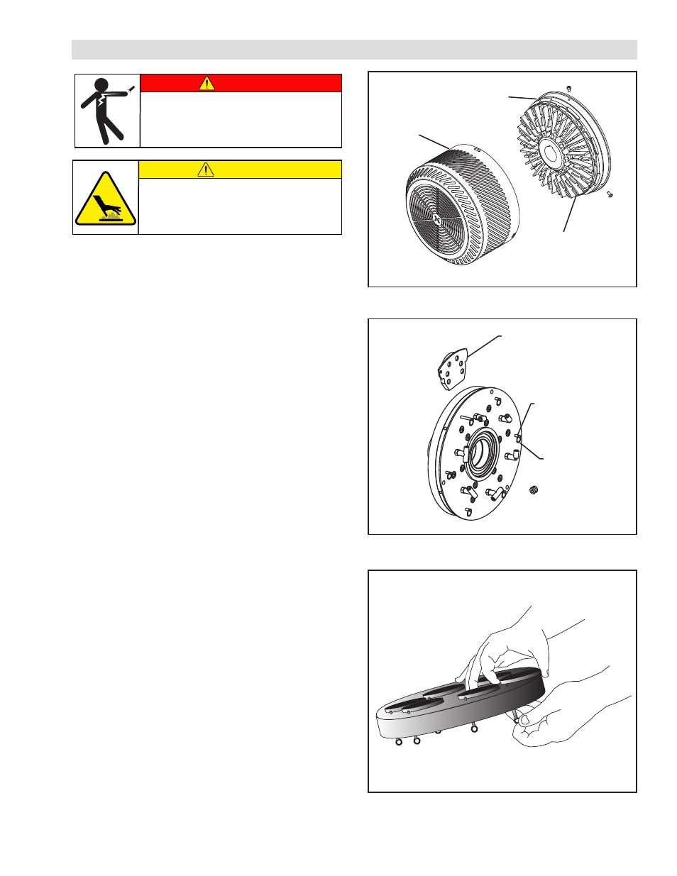
Refer to Figures 7 - 9.
1. Loosen the Pan Head Screws (Item 11) in the Endcap
(Item 3).
NOTE: Do not remove Pan Head Screws (Item 11)
completely from the Endcap.
2. Remove the Guard (Item 12) from the Endcap (Item
3).
3. Release a Friction Facing Assembly (Item 4) by pulling
the Ring or Finger Nut (Item 42) that is attached to
Retaining Pin (Item 7).
4. Slide the old Friction Facing Assembly (Item 4) out of
the BTBA.
5. Slide a new Friction Facing Assembly (Item 4) into the
BTBA.
6. Release the Ring or Finger Nut (Item 42) that is
attached to the Retaining Pin (Item 7). The Retaining
Pin (Item 7) locks the new Friction Facing Assembly
(Item 4) securely in place.
7. Repeat these steps until you have replaced all six
(BTBA-10) or eight (BTBA-12) of the Friction Facing
Assemblies (Item 4).
8. Reinstall the Guard (Item 12) to the Endcap (Item 3)
and hand tighten the Pan Head Screws (Item 11).
FRICTION FACING ASSEMBLY
Figure 9
Figure 7
Pan Head Screw
(Item 11)
Endcap
(Item 3)
Guard
(Item 12)
Figure 8
( or Finger Nut)
Friction Facing
Assembly
(Item 4)
Ring
(Item 42)
Retaining Pin
(Item 7)
DANGER
Remove all power from the fan
BEFORE removing the Guard.
Hazardous Voltage.
Will cause severe injury or death.
CAUTION
Surface temperature may exceed
safe handling limits during
operation. Do not touch.
- BTBA-12 927524 BTBA-12 927544 BTBA-10 927408 BTBA-10 927421 BTBA-10 927420 BTBA-10 927423 BTBA-10 927422 BTBA-10 927425 BTBA-10 927424 BTBA-10 927427 BTBA-10 927426 BTBA-10 927429 BTBA-10 927428 BTBA-10 927431 BTBA-10 927430 BTBA-10 927432 BTBA-10 927407 BTBA-10 927440 BTBA-10 927439 BTBA-10 927433 BTBA-10 927441 BTBA-10 927438 BTBA-12 927523 BTBA-12 927526 BTBA-12 927525 BTBA-12 927528 BTBA-12 927527 BTBA-12 927530 BTBA-12 927529 BTBA-12 927532 BTBA-12 927531 BTBA-12 927534 BTBA-12 927533 BTBA-12 927536 BTBA-12 927535 BTBA-12 927538 BTBA-12 927537 BTBA-12 927546 BTBA-12 927545 BTBA-12 927509 BTBA-12 927507