Limit switch adjustment – Nexen Size 18 964104 User Manual
Page 9
3
FORM NO. L-20244-D-0300
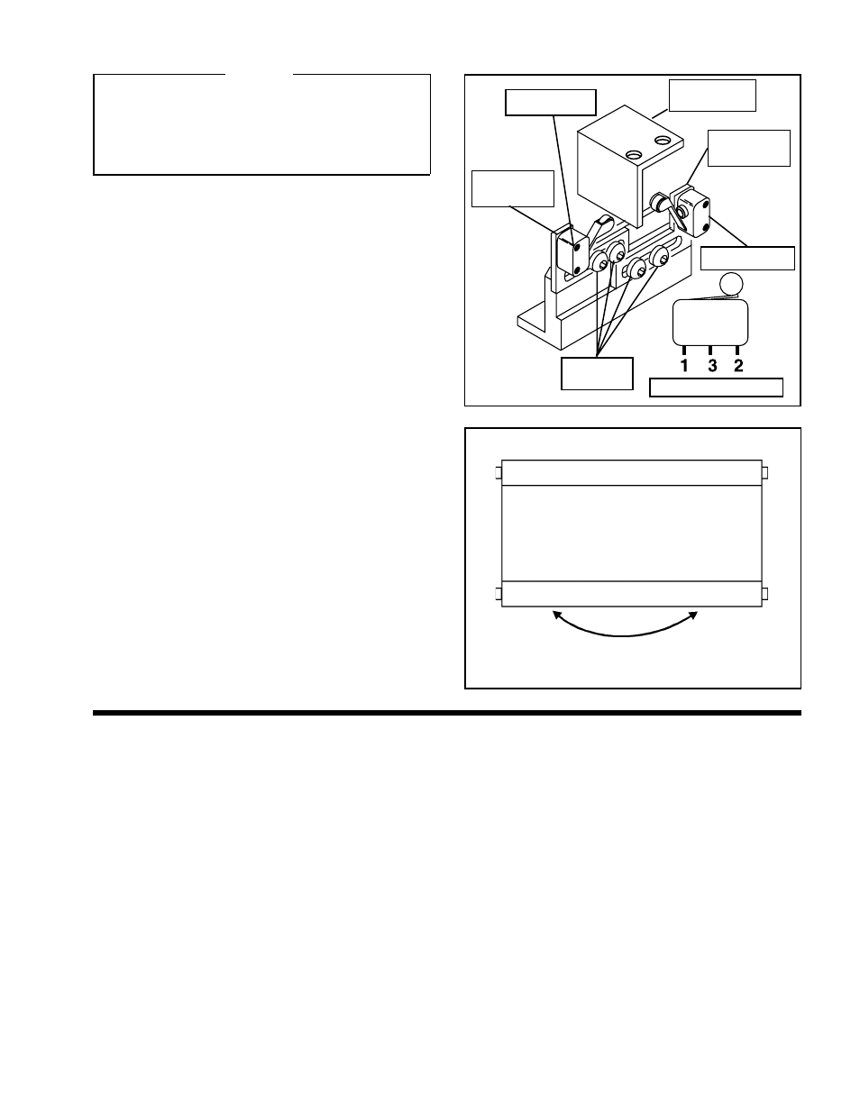
LIMIT SWITCH ADJUSTMENT
CAUTION
The Limit Switches have been set by Nexen for
maximum travel. Limit Switches must be adjusted to
interrupt movement before contact is made with a
physical obstruction or stop. If there is no obstruction,
the Limit Switches should remain in their factory set
positions for maximum travel.
1.
Loosen the Pan Head Screws holding the Limit
Switch Brackets and slide the Limit Switch Brackets
and Limit Switches to their fully extended positions
(See Figure 7).
2.
Turn "ON the web guide controller and set it to the
manual control mode.
3.
Using the web guide controller's push buttons, rotate
the web guide in one direction until the desired end of
travel is reached (See Figure 8).
4.
Connect a voltmeter across Terminals 1 and 2 of the
Limit Switch (See Figure 7) that will limit the web guide
movement in the direction just moved.
5.
Slide the Limit Switch towards the Limit Switch Stop
Plate until the Limit Switch is activated by the Limit
Switch Stop Plate and the voltmeter reads
±
5 volts.
6.
Tighten the Limit Switch Bracket's Pan Head Screws
(See Figure 7).
7.
Repeat Steps 3 through 6 for the second Limit Switch.
8.
Turn the web guide controller "OFF".
Limit Switch
Stop Plate
FIGURE 7
Limit Switch
Bracket
Limit Switch
Terminal Locations
Limit Switch
Limit Switch
Bracket
Pan Head
Screws
FIGURE 8