Electrical connections, Base mounting, Manifold mounting – Nexen EN40-2B 912004 User Manual
Page 5
FORM NO. L-20097-F-0605
(5)
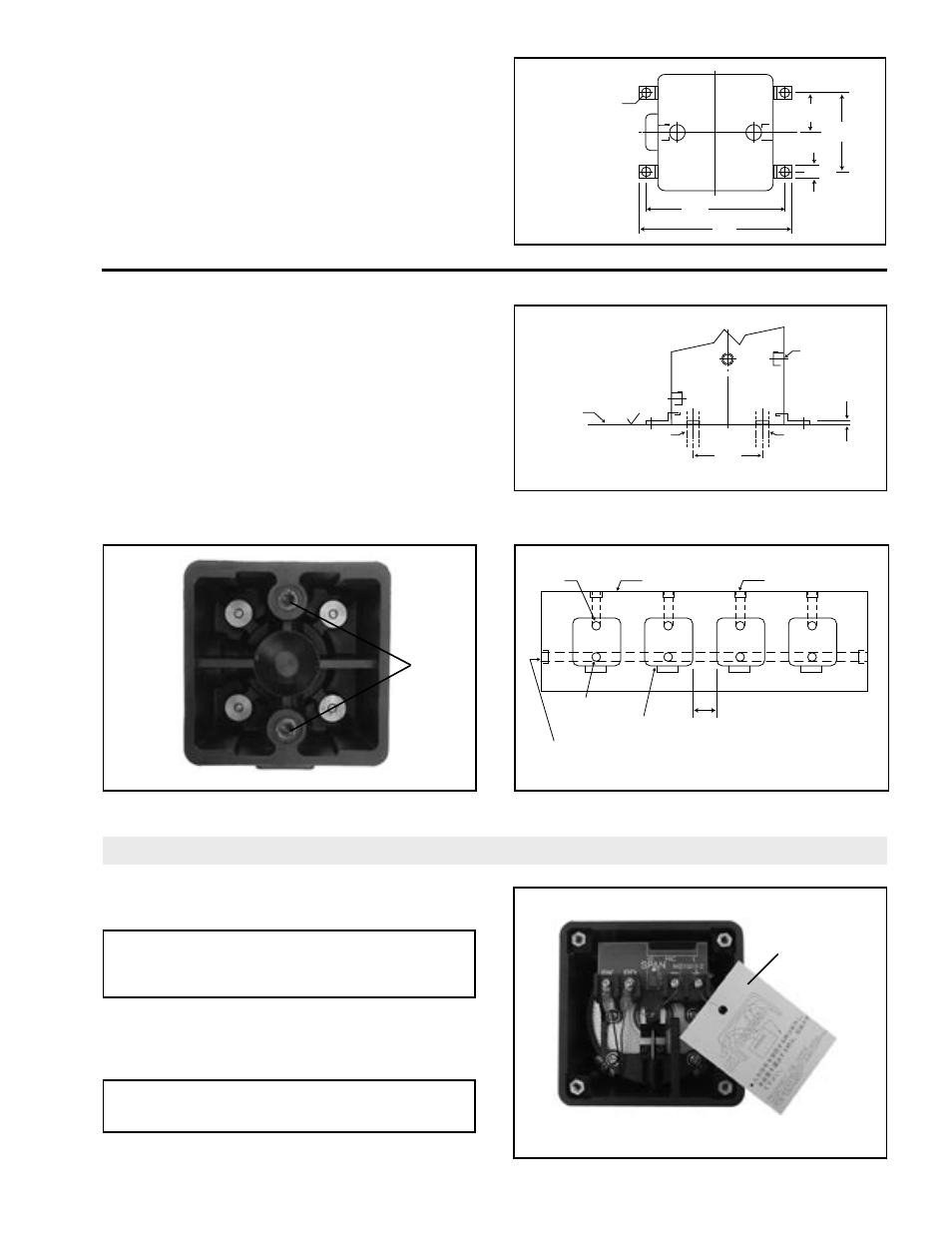
ELECTRICAL CONNECTIONS
1. Remove cover from EN40, then remove
WARNING Tag “INPUT” terminals (See Figure 7.)
CAUTION
Always short “INPUT” terminals when
transporting or storing “EN40.”
2. Using customer supplied 18AWG wire, connect
EN40 to controller (See Figure 8), routing wire
through threaded conduit hole on side of “EN40.”
CAUTION
Always observe polarity of terminals.
FIGURE 7
BASE MOUNTING
1. Remove “EN40” Wall Mounting Bracket.
2. Secure “EN40” to base using Brackets and M5
Cap Screws provided in parts bag (See Figure 3.)
FIGURE 3
MANIFOLD MOUNTING
1. Remove “EN40” Wall Mounting Bracket.
2. Plug “INLET” and “OUTLET” ports with Plugs
provided in parts bag.
3. Remove Plugs from underside of EN40 and install
O-rings provided in parts bag (See Figure 4).
4. Secure “EN40” to Manifold using Brackets and
M5 Cap Screws provided in parts bag (See Figure
5 & 6).
FIGURE 4
FIGURE 5
FIGURE 6
Remove
Plugs &
Install
O-rings.
Remove
WARNING
Tag.
4.645
[118]
5.04
[128]
0.48
[12.2]
2.638
[67]
1.319
[33.5]
[4] Brackets &
[4] 5mm Screws
Provided (or use
[4] #10 Screws)
125
MANIFOLD
PLUG
2 Provided
2.362
[60]
OUT
0.250
[6.35]
Dia. Max.
IN
0.250
[6.35]
Dia. Max.
0.13
[3.3]
1.57 [39.9] Min. should be maintained
when installing two or more converters.
OUTPUT
EN40-IS
IN
SUPPLY
OUT
MANIFOLD