Nexen TCB07 835186 User Manual
Page 8
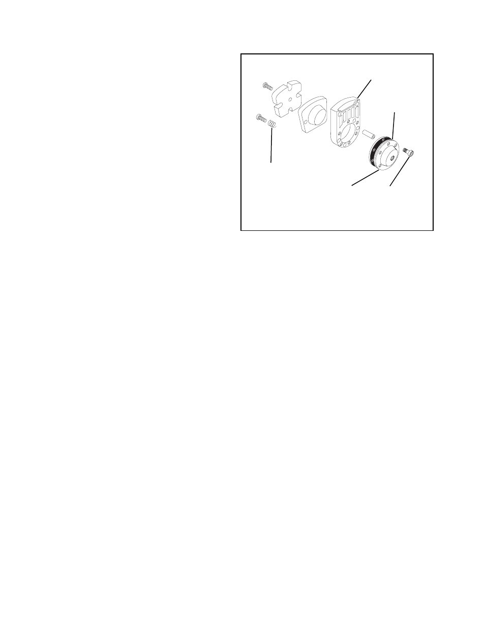
5
FORM NO. L-20169-D-0501
DIAPHRAGM
1.
Proceed with Steps 1 - 4 of PARTS REPLACE-
MENT—FRICTION FACINGS.
2.
Remove the six Socket Head Cap Screws (Item 20)
and Cover (Item 13) from the Cylinder (Item 11)
(See Figure 8).
3.
Remove Diaphragm (Item 14) (See Figure 8).
NOTE: Internal Compression Springs (Item 41)
may also be removed at this time. These
springs are optional; the low air pressure
setting is more sensitive without the springs
(See Figure 8).
4.
Install a new Diaphragm with the rubber (not fabric)
on the air side and reassemble the Caliper
Assembly.
5.
Tighten the Socket Head Cap Screws (Item 20) to
5.5 Ft. Lbs. [7.45 N•m] torque (See Figure 8).
6.
Proceed with Steps 7 - 9 of PARTS REPLACE-
MENT—FRICTION FACINGS.
FIGURE 8
Cylinder
(Item 11)
Diaphragm
(Item 14)
Compression
Spring
(Item 41)
Cover
(Item 13)
Socket Head
Cap Screws
(Item 20)