Bodypack transmitter, Parts names and functions, Operating manual – MIPRO ma705(2ce161) User Manual
Page 17
Operating Manual
MIC
12
5
4
1 0
OFF
9
8
11
6
7
12
ON
BATT.LOW
1 0
9
8
(PHONEJACK)
2
11
BATT.LOW
ON
OFF
12
1 0
9
7
6
8
11
OFF
ON
BATT.LOW
3
2
MIC
ANT.
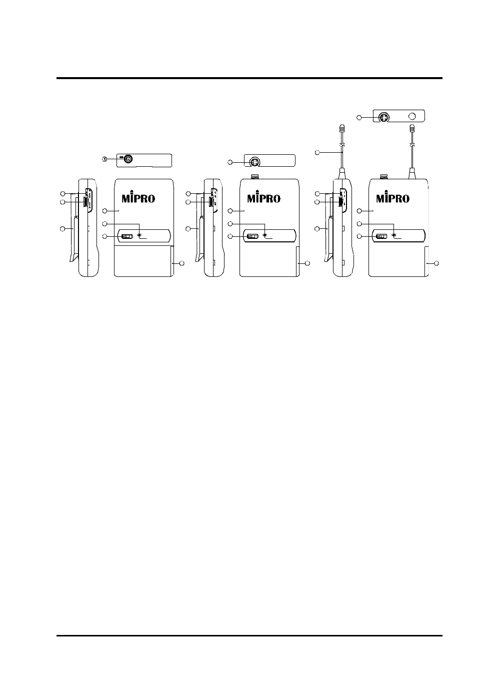
1. PARTS NAMES AND FUNCTIONS
BODYPACK TRANSMITTER
1. Audio Input Connector: Phone-jack connector accepts lavalier and head worn
microphones.
2. Audio Input Connector: 4-pin connector accepts a variety of input levels (consult the
audio input connection wiring detail. Diagram 3).
3. Transmitting Antenna: 1/ 4
transmitting antenna.
4. Fixed Volume Switch: When in the up position, it will lock the volume at a fixed
level.
5. Volume Control: Adjusts the volume level.
6. GT/MT Level Selector: Set this switch to GT (Guitar) position if you are connecting
to the output of an electric guitar. Set the switch to the MT (microphone) position for
all other connections.
7. Input Gain Control: Works only in the MT (microphone) position and allows users to
control input level.
8. Transmitter Housing: Lightweight, compact, durable high-impact plastic for maximum
comfort. Covers and protects PCB and other components.
9. Battery Status Indicator: Flashes briefly at turn-on to indicate that the battery is OK.
No flash at turn-on indicates that the battery is either drained or not installed
properly. A constant glow indicates a weak battery that should be replaced.
10.Power Switch:Turns power "on" and "off" of the transmitter .
11.Battery Compartment and Cover: Accept a 9-volt alkaline battery.
12.Detachable Belt Clip: To detach for pocket use, push in the direction of the arrow
while lifting up on the tab. To install: Align the flanges on the clip with the tracks on
the transmitter. Slide the clip upward to the connector until it snaps into place.
λ
- 1 5 -
(4PINJACK)
(UHFTRANSMITTER)