Belt pack transmitter – MIPRO mr801(2ce126)a2 User Manual
Page 7
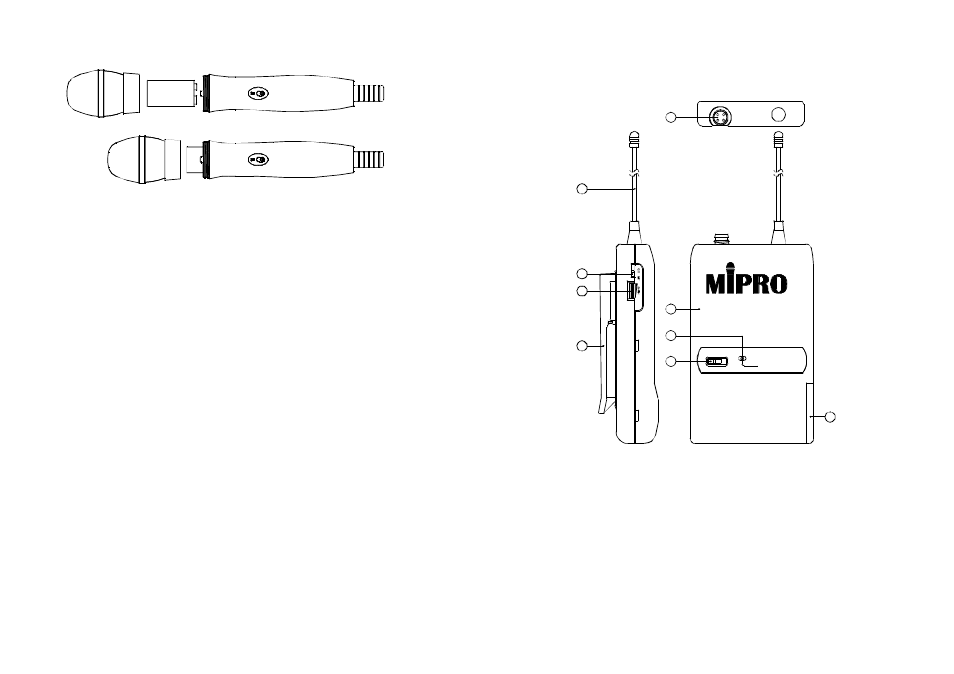
1. 4-Pin Jack Input Connector: Connect to 4-pin connector. Allows 5
different inputs. (See 5 ways of connection on AF Input Connections
later in this booklet).
2. Transmitting Antenna: 1/ 4
transmitting antenna.
3. GT/MT Switch:Switch to the GT position for electric guitar u sage
ONLY. The Gain Control is bypassed in "GT" mode. Switch to the
"MT" for condenser microphone, wired microphone or Line-in. The
Gain Control operates in the"MT" mode for adjusting input sensitivity.
4. Gain Control: Adjusts the input gain. Please take care not to
inadvertently turn the level down for a loss of signal, or up to induce
feedback.
λ
BELT PACK TRANSMITTER
1. Parts Name And Functions
- 1 1 -
- 1 2 -
1. Unscrew battery cap in counter-clockwise direction (Fig. 2).
2. Insert a 9V battery into the battery compartment according to the
correct polarity as shown in Fig.2. The m o ment thebattery touches
the terminals of compartment, the indicator (5) will flash briefly. This
means the polarity is correct. However, if noflash occurs, this
indicates wrong insertion. Please re-insert the battery according to its
correct polarity.
1. When m icrophone is switched on:
At the moment of the power is switched on, the indicator will flash
briefly indicating normal operation.
2. After microphone isswitched on:
The SIGNALLEDindicator (3) o f receiver glows. The more LED
glows indicating received signal strength is stronger. If only red LED
illuminates it denotes abnormalreceiving status.
3. DuringUsage:
The AUDIO LED indicator (4) of the receiver will illuminate according
to the soundstrength input to the microphone. When approaching
red LED lights on, it denotes the maximum soundpress level but
does not represent distortion.
4. When the microphone is n o t in use:
Make sure to turn o f f the microphone to extend the battery life.
Remove the battery from the battery compartment if microphone is
not in used. If a rechargeable battery was used, take it out and
insert to the built-in battery charger o n t h e receiver for recharge.
2. Battery Insertion
3. Operating Instructions
(Fig.2)
MIC
ANT.
BATT.LOW
OFF
ON
1
2
3
4
5
6
7
8
9