Single channel wireless receiver – MIPRO mr515a(2ce228) User Manual
Page 4
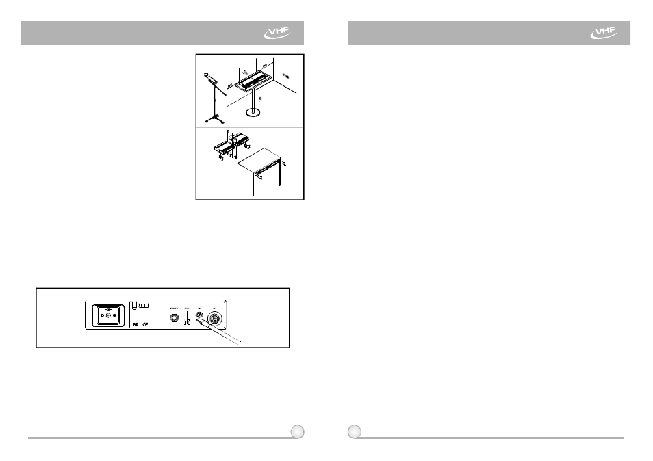
4.
Make sure the system performs correctly,
pleaseplacethe system away from noise
sources. Place the receiver at least 1
meter above the ground and away from
noise sources. Place the microphone at
least 1 meteraway from the receiving
antenna, as shown in Fig. 6.
5.
With two rackmountbrackets installed,
receiver can be mounted into anEIA
standard rackmount case, as shown in
Fig. 7. As an accessory, you may
purchase fromnearest dealer a front
antenna kit, which not onlyallowseasy
front antenna installation, but also
improves efficiency of signal reception.
1.
Turn volume controlsofthereceiver andmixerin use to a minimum setting
before turn onthe microphones or transmitters. After switches onthe
receiver, the power switch red indicator illuminates to denotenormal power
status.
3.
Under normal circumstances, the SIGNAL indicatorlightsup when a
microphone o r t r ansmitter is turned on near the receiver to indicate the
receiver isreadyfor normal operation. Oncesounds to the microphoneand
the AUDIOLED indicators (4) will glow according to the strengthof sound
level. If noLED glows or no sound outputs, t h e s ystem is not function
properly, thus it must bechecked.
4.
Receiver and Amplifier VolumeAdjustment:
5
6
Fig.7
Fig.8
Fig.6
4. OPERATION INSTRUCTIONS
SINGLE CHANNEL WIRELESS RECEIVER
SINGLE CHANNEL WIRELESS RECEIVER
Ground
+
-
0dB
+10dB
- 6 d B
2.
If SIGNAL LED indicators (3) of the receiver light on before switches on the
microphone or transmitter, it indicates the receiver is receiving interference
signals. This system has Pitlotone and NoiseLock d ual-squelch features
and no noiseoutputwill occur. Ifmultiple channels are used and both
SIGNAL and AUDIO LEDsglow and interference noise appear, simply
adjust the Squelch controls (7) clockwiseuntil AUDIO signalindicators to
extinguish. (Fig. 8). However, byadjusting the squelch controls, it affects
the sensitivity level of the receiver, therefore, shorten the operating distance
and decreases the stability.
(a) Unbalanced Audio Output: S witch the level switch (6) onthe receiver
rear panel to the left position "MIC", thenadjustvolumecontrol of the
amplifier or mixer to obtain an appropriate sound level of the
microphone.
(b) To obtainsamesensitivity and volume level of both wired andwireless
microphones in a mixer or amplifier that has more than 2 microphone
input sockets, one canadjustthe wired microphone volume control in
the mixeror amplifier. After reaching desired sound level, connect t o
theAF output socket of receiver. Please note that the unbalanced
volume switch on the back o f t h e receiver should switchto "MIC"
position.
(c) If the receiver output level is adjusted excessively, it w ill cause the
saturation distortion ofthe mixer or amplifier when the microphone is
loud.