Display, Rear panel – Alto Professional Radius 200 User Manual
Page 7
7
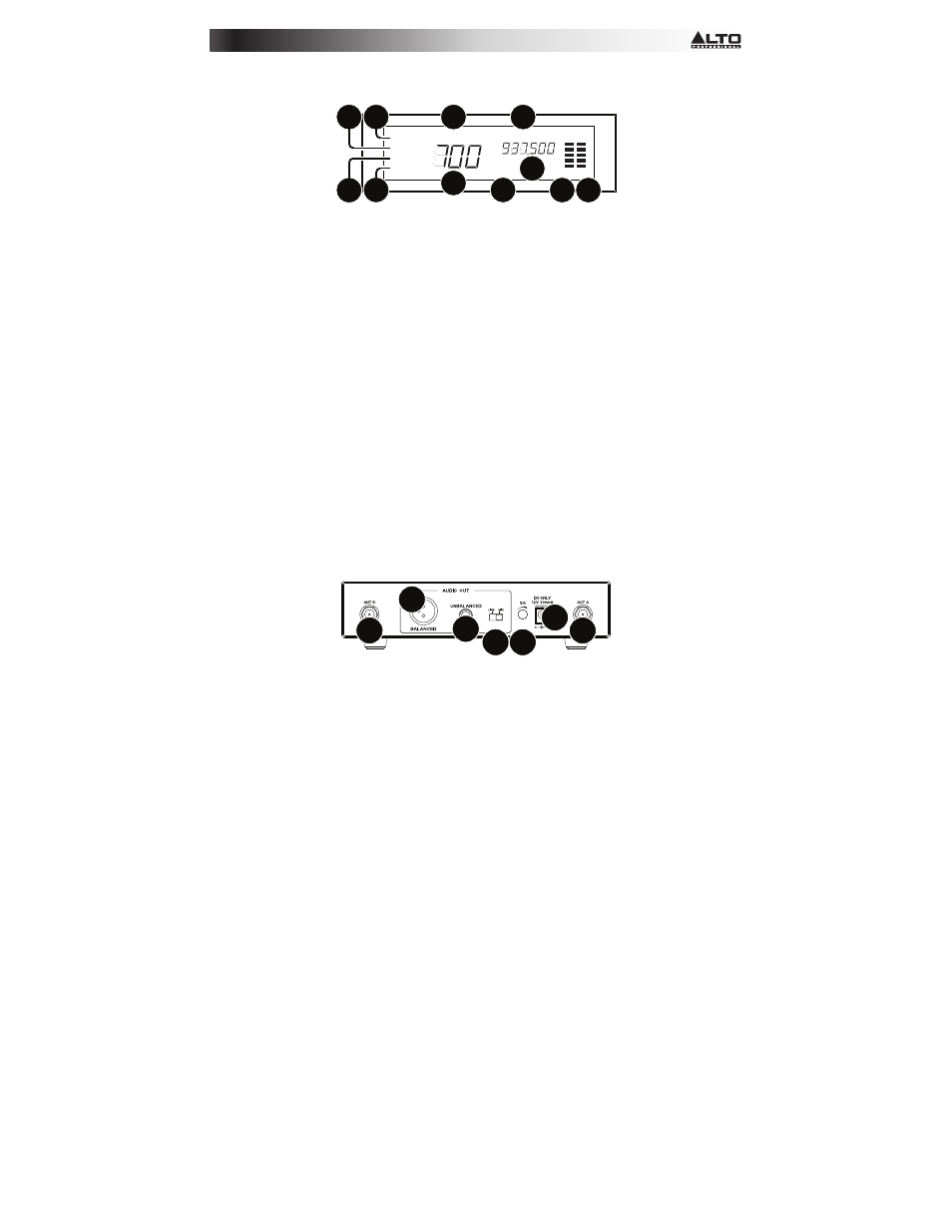
Display
MANUAL
GP
CH
SCAN
PRESET
SYNC
CH
MUTE
RF AF
FREQ
MHz
P1 P2 P3 P4
1 2 3 4 5 6 7 8
1
5
7
6
2
3 4
10 11
9
8
1.
Manual: This indicator appears when the receiver is in Manual Mode, where you can select
the channel manually. Use the Up/Down buttons to cycle between the different modes.
2.
Scan: This indicator appears when the receiver is in Autoscan Mode, where the receiver
automatically selects the channel with the clearest and strongest reception.
3.
Preset: This indicator appears when the receiver is in Preset Mode, where you can select
a Preset group of channels rather than having to scan the entire frequency band.
4.
Sync: This indicator appears when the transmitter and receiver are synchronized.
5.
GP (P1, P2, P3, P4): This is the current Preset group.
6.
CH (1–8): This is the current Preset Channel.
7.
CH (region-specific): This is the current channel number. The number of available
channels depends on your region.
8.
Freq: This is the current frequency in MHz.
9.
Mute: This indicator appears when the audio signal is muted.
10.
RF: This meter shows the current level of reception between the transmitter and receiver.
11.
AF: This meter shows the current audio signal level sent from the receiver’s audio outputs.
Rear Panel
1
1
2
6
3
4 5
1.
Antenna Terminal: Connect the included antennae to these terminals.
2.
Audio Output (XLR): Use a standard XLR cable to connect this balanced output to your
guitar amplifier, mixer, PA system, etc.
3.
Audio Output (1/4” / 6.35 mm): Use a standard 1/4” (6.35 mm) cable to connect this
unbalanced output to your mixer, PA system, etc.
4.
Line/Mic Selector: Use this switch to select whether the signal from the receiver’s output
is line-level or microphone-level. Set this switch to Line if you are connecting it to a
balanced line-level input (e.g., a mixer’s XLR or 1/4” TRS input) or an instrument amplifier’s
low-impedance active instrument input. Set this switch to Mic if you are connecting it to
an instrument amplifier’s high-impedance instrument-level input.
5.
Squelch: Turn this knob to adjust the noise floor level.
6.
Power Input: Use the included power adapter (12 V, 1 A, center positive) to connect this
input to your power source.