2 connecting the cables, 2-1 serial interface (rs-232c), Srp-340 – BIXOLON SRP-340 User Manual
Page 8: Rev. 1.02, Ifa-s type
Rev. 1.02
- 8 -
SRP-340
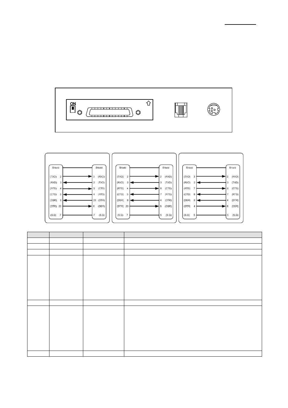
1-2 Connecting the Cables
You can connect up the three cables to the printer. They all connect to the connector panel
on the back of the printer, which is shown below:
※ NOTE
Before connecting any of the cables, make sure that both the printer and the host are
turned off.
1-2-1 Serial Interface (RS-232C)
※
When the Dip Switch is “ON” on the Serial Interface Board,
DTR and RTS are connected each other.
Pin No.
Signal Name
Signal Direction
Function
BODY
Frame GND
-
Frame Ground
2
TXD
Output
Transmit Data
3
RXD
Input
Receive Data
6
DSR
Input
This signal indicates whether the host computer can receive
data. (H/W flow control)
1) MARK(Logic1) : The host can receive a data.
2) SPACE(Logic0) : The host can not receive a data.
3) The printer transmits a data to the host, after confirming
this signal.
4) When XON/XOFF flow control is selected, the printer
does not check this signal.
7
Signal GND
-
Signal Ground
20
DTR
Output
This signal indicates whether the printer is busy. (H/W flow
control)
1) MARK(Logic1) : The printer is busy.
2) SPACE(Logic0) : The printer is not busy.
3) The host transmits a data to the printer, after confirming
this signal.
4) When XON/XOFF flow control is selected, the host does
not check this signal.
Shield
Frame GND
-
Frame Ground
IFA-S TYPE
Drawer kick-out
connector
Power supply
connector
Interface connector
PRINTER
SIDE (25P)
HOST
SIDE (25P)
PRINTER
SIDE (25P)
HOST
SIDE (9P)
PRINTER
SIDE (9P)
HOST
SIDE (9P)