14 <switch and indicator – COMMELL LV-67O User Manual
Page 32
Advertising
LV-67O User’s Manual
-
32
-
Connector:
CPUFAN
Type: 4-pin fan wafer connector
Pin
Description
Pin
Description
1 Ground
2 +12V
3
Fan Speed Detection
4
Fan Control
Connector:
SYSFAN
Type: 4-pin fan wafer connector
Pin
Description
Pin
Description
1 Ground
2 +12V
3
Fan Speed Detection
4
Fan Control
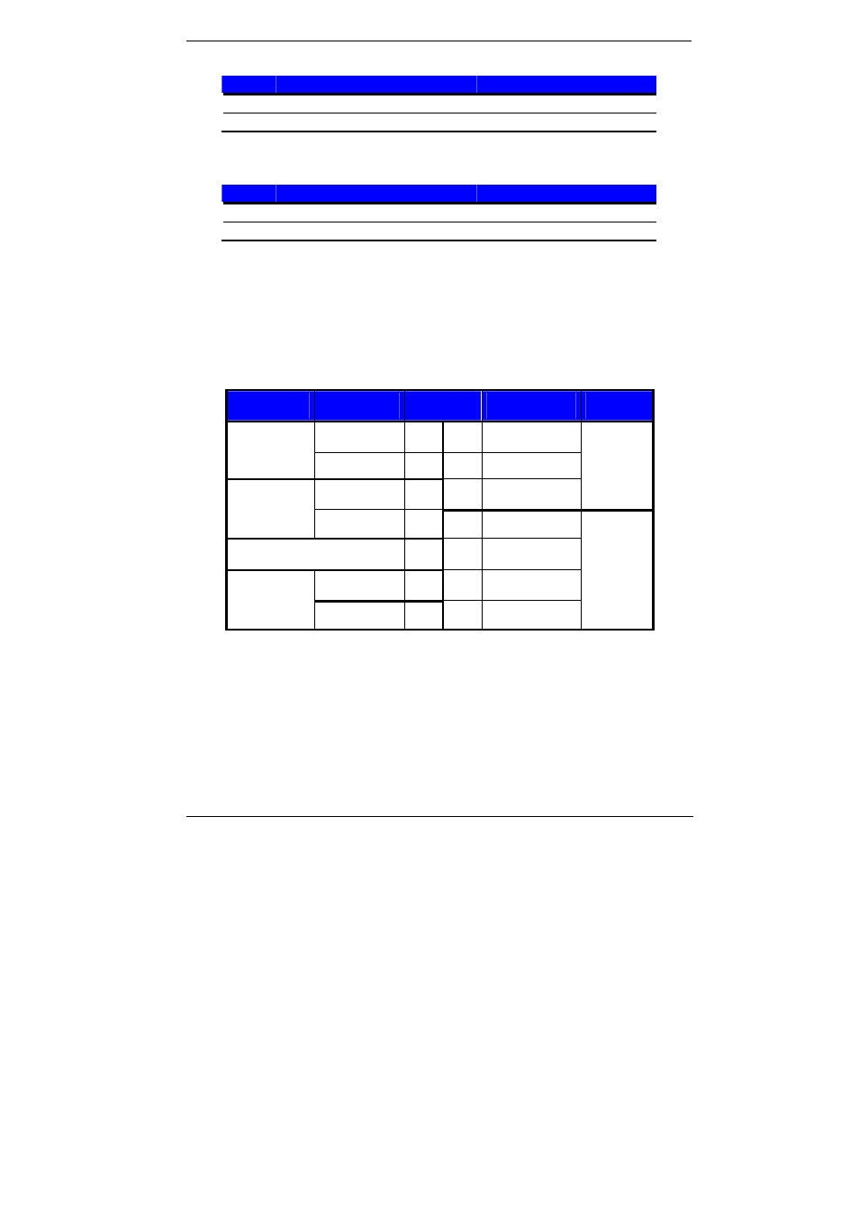
2.14 <Switch and Indicator>
The
JFRNT provides front control panel of the board, such as power button, reset and
beeper, etc. Please check well before you connecting the cables on the chassis.
Connector:
JFRNT
Type: onboard 14-pin (2 x 7) 2.54-pitch header
Function
Signal
PIN
Signal
Function
HDLED+ 1
2 PWRLED+
IDE LED
HDLED- 3
4 N/C
Reset+ 5
6 PWRLED-
Power LED
Reset
Reset- 7
8 SPK+
N/C 9
10
N/C
PWRBT+ 11
12
N/C
Power Button
PWRBT- 13
14
SPK-
Speaker
Advertising