Connections, Operation, Controller settings – d&b Y7P User Manual
Page 6
2.2. Connections
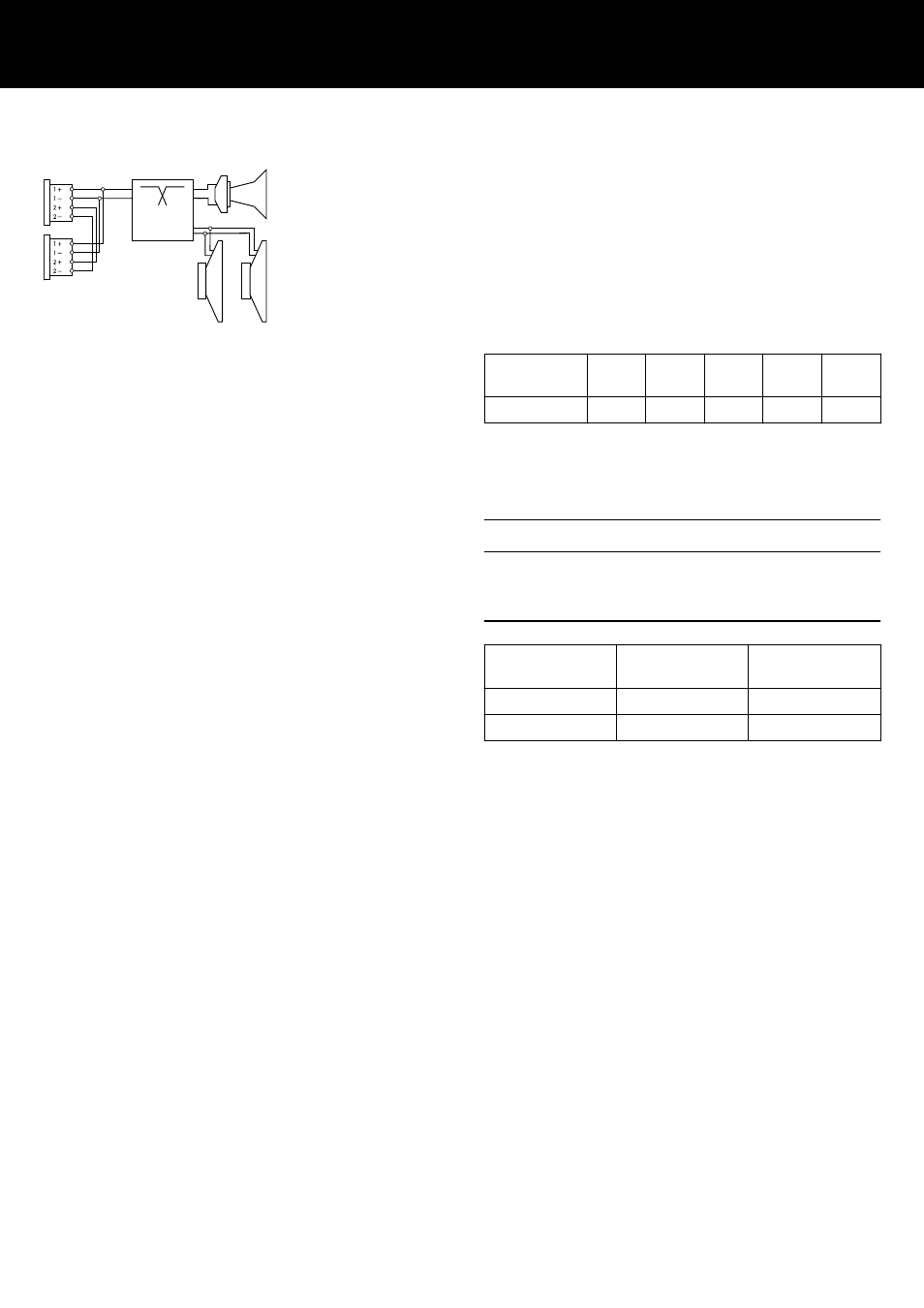
The cabinets are fitted with a pair of NLT4 F/M connectors. All
four pins of both connectors are wired in parallel. The cabinets use
the pin assignments 1+/1–. Pins 2+/2– are designated to active
subwoofers. Using the male connector as the input, the female
connector allows for direct connection to a second cabinet.
The cabinets can be supplied with NL4 M or EP5 connectors as an
option.
Pin equivalents of the connector options are listed in the table
below.
NLT4 F/M
NL4 M
1+
1–
2+
2–
n.a.
EP5
1
2
3
4
5
2.3. Operation
NOTICE!
Only operate d&b loudspeakers with a correctly configured d&b
amplifier, otherwise there is a risk of damaging the loudspeaker
components.
Application
Setup
Cabinets per
channel
Y7P
Y7P
2
Y10P
Y10P
2
For applicable amplifiers, the controller setups are available in
Dual Channel and Mix TOP/SUB mode.
2.3.1. Controller settings
For acoustic adjustment the functions CUT, HFA and CPL can be
selected.
CUT circuit
Set to CUT, the cabinet low frequency level is reduced. The
cabinets are now configured for use with actively driven d&b
subwoofers.
passi
ve
crossover
Connector wiring
d&b Y7P/Y10P Manual 1.2 en
6