Data acquisition system, Probe compensation generator, Power – Dataman 520 Series User Manual
Page 88: Insulation specification
DATAMAN oscilloscope
User’s Guide
Adjustments
Digital filter with ability of setting the valid pulse length
up to 131072*Ts for each level and counter of valid
triggering events selectable from 1 to 32768 for each
level. HOLD-OFF selectable up to 1048576*Ts with
selectable AUTO mode, to sample proper amount of data
before trigger. (Ts – actual real time sampling period)
Table 7.3.2.1. – Triggering
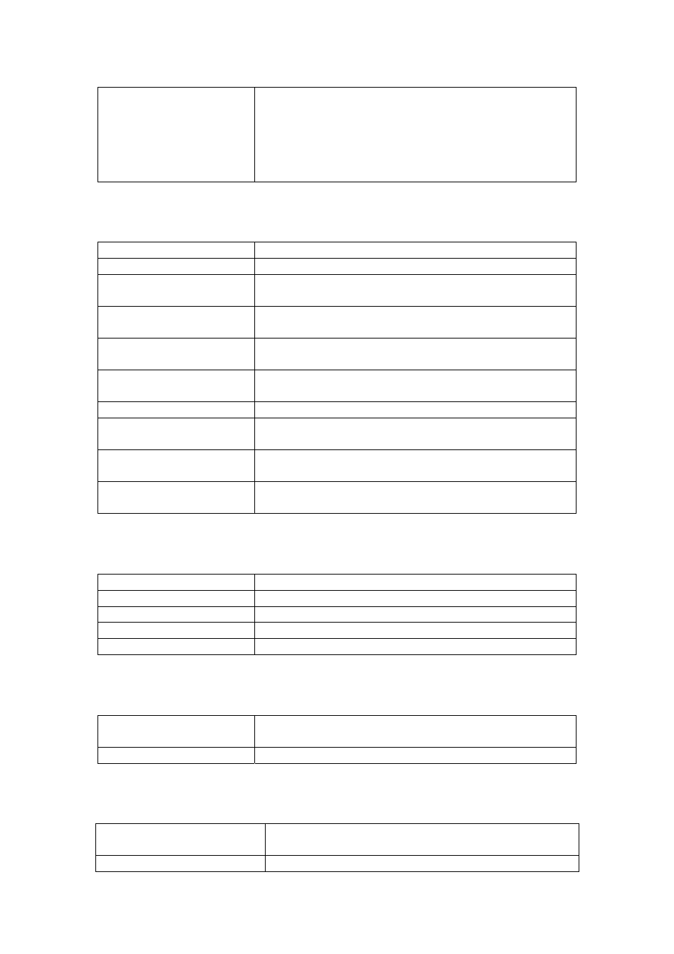
7.3.3. Data acquisition system
No of divisions
10
No of pixels per division
50
Mode of operation
Sampling before and after trigger with continual
selection of the trigger position
Record length
selectable from 1024 to 1048576 (1M) samples for each
channel
Time base range in 1:1
mode
5 ns/d to 100 ms/d in 1-2-5 sequence
Time base range using
different ZOOM modes
625 ps/d to 204.8 s/d
Time base accuracy
0.01 % to 100ns/d, 0.5 % for 50ns/d to 5 ns/d
Real time sampling
frequency
500 Hz to 100 MHz
Equivalent sampling
frequency
500 Hz to 10 GHz
Display range with respect
to trigger event
1048576 samples before and 1048576 samples after trig.
event in length of 1048576 samples
Table 7.3.3.1. – Data acquisition system
7.3.4. Probe compensation generator
Output connector
BNC, together with External trigger input
Output impedance
1 kOhm to parallel with 10nF and approx. 50 Ohm serial
Output waveform
Pulse with 1:1 duty cycle
Frequency 1465
Hz
Output voltage (no load)
3.3V +- 5%
Table 7.3.4.1. – Compensation generator
7.3.5. Power
Power source
USB interface via USB cable (power ground isolated
from ground of measuring inputs)
Max current
470mA
Table 7.3.5.1. – Power
7.3.6. Insulation specification
Maximum working voltage
500Vp while the voltage [V] * frequency [Hz] factor
must not exceed 50000 [V Hz]
Resistance
> 2 GOhm
- 88 -