Input power, Mounting, Wir ing – ILUMINARC Ilumiline™ LΩGIC 12 User Manual
Page 3: Connectivity
Ilumiline LΩgic™ 12 RGB
3
Input Power
The input power for this product is provided by a L
Ω
gic™ Controller
(
1,050 mA @ 48 V).
Mounting
The Ilumiline LΩgic™ 12 RGB includes mounting hardware with
6.3-mm holes, which allow the product to be mounted on any flat
surface. Once mounted, the angle can also be adjusted.
Wir
ing
This product comes with a 79 in (2 m) long CAT 5 cable, terminated
with an RJ45 plug to connect to a L
Ω
gic™ Controller. If using the
included splitter or if making an extension of the product’s cable, you
must use plenum-grade CAT 5/6 wire. The RJ45 connector pin out is
shown below.
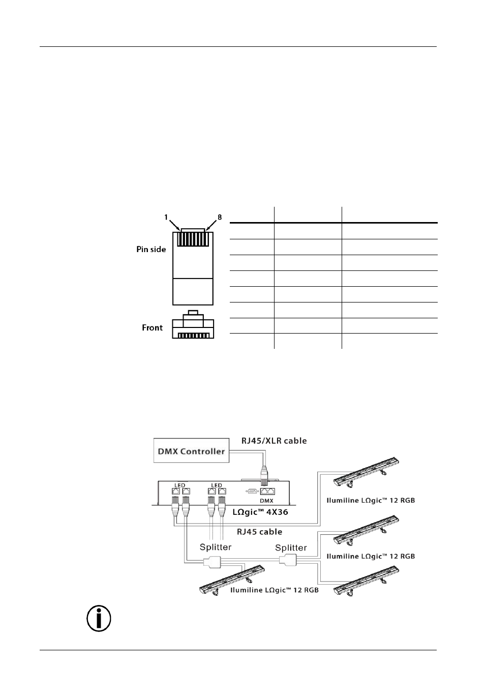
RJ45 Pin Out
Pin
Wire Color
Function
1
White/orange Red LED +
2
Orange/white Green LED +
3
White/green Blue LED +
4
Blue/white
Not used
5
White/blue
Red LED -
6
Green/white Green LED -
7
White/brown Blue LED -
8
Brown/white Not used
Connectivity
The figure below shows a possible connection layout using this product
and a L
Ω
gic™ 4X36 Controller. Refer to the applicable L
Ω
gic™
Controller User Manual regarding wiring layouts and limitations.
Connection Diagram
All cables must be terminated to a product. Do not use
the splitter as a coupler.