10 crossover: wiring diagram e 90 mk ii, Crossover: wiring diagram e 90 mk ii – KLING & FREITAG K&F E 90 MK II User Manual
Page 16
User’s Manual
E 90 MK II
KLING & FREITAG GMBH ©1995 - 2006
Version 4.0, 02.11.2006
Page 16 of 22
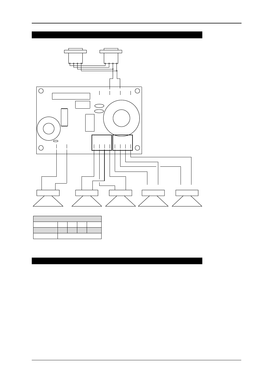
10.
Crossover: Wiring Diagram E 90 MK II
2+
IN +
IN -
2- 1+ 1-
2+ 2- 1+ 1-
+
-
HF
+
-
LF 1
+
-
LF 2
+
-
LF 3
+
-
LF 4
+
-
HF
-
-
+
+
-
-
+
+
LF 1 + 2
LF 3 + 4
-
-
+
+
IN
11.
Touching Up Damage to Paint / Changing the Front Foam
Although the PU structured paint used by KLING & FREITAG is impact proof and ex-
tremely resistant, we recommend using protective coverings or cases to help avoid
damaging the paint during i.e. continuous mobile use. If paint damage occurs despite
these precautions, it can be touched up by using commercial acrylic paint in the ap-
propriate RAL colour of the speaker.
To replace the filter foam, send the front grille incl. foam to KLING & FREITAG GmbH.
Upon payment for expenses, the grille with the new covering will be returned.
Pin assignment Speakon NL4
+
-
/
/
‘IN’
1+ 1-
2+ 2-
‘OUT’
parallel with ‘IN’