Round connections – OT Systems FTD100Micro User Manual
Page 8
Advertising
FTD100Micro Series Installation & Operation Manual
8
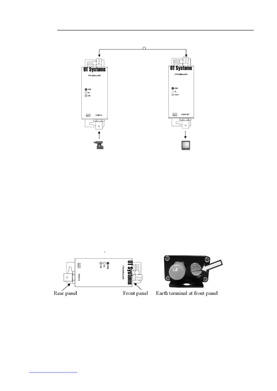
Typical System Cable Connections Diagram:
Micro Transmitter
Micro Receiver
Fig 4.1 Micro to Micro unit connection diagram
4.2 Ground connections
For enhanced safety to reduce the risks of electrical shock and physical damage, caused by
lightning and other power surges, as well as a connection to the surge suppresion devices in the
product, a screw terminal is provided on the Micro cabinets (Fig. 4.4). It is highly recommended
that the Micro unit have good ground connections to the buildings ground in accordance with the
local codes.
Fig. 4.4 Micro unit earth terminal location
Advertising