Oxmoor MPM-81 User Manual
81 microphone preamp/mixer, Mpm-81 microphone preamp/mixer
Oxmoor Corporation, LLC, 309 Cahaba Valley Parkway, Birmingham, AL 35124 USA Toll Free: 1-800-262-6898
Phone: 205-982-8200 Fax: 205-982-8250 E-mail: [email protected] Internet: www.oxmoor.com
nels can be assigned to the Mix Bus
except the channel that is selected as
the Page channel. When the Page chan-
nel is activated, it is routed to the Mix
Bus. All channels except the Page chan-
nel will then mute their audio if they
have been programmed to mute. Upon
completion of the page, all channels
return to their previous levels.
A control port provides connection for
remote volume control of channels 1 - 8
and the Mix Bus master volume. Each
remote volume control requires a 10K
pot and a DC voltage between +15
“Off” and 0 VDC “Full On.”
The compact 1U rack space MPM-81
brings simplicity to system design,
installation and operation, along with
the uncompromising performance and
reliability for which Oxmoor products
are known.
The MPM-81 Microphone Preamp Mixer
provides eight balanced microphone/
line level inputs. Each input can be
switched between microphone level or
line level.
There are eight Direct outputs and one
Mix Bus out. Each input can easily be
routed to the Mix Bus using a dedicated
control line for remote applications or
an internal dip switch for permanent
assignment. Any combination of the eight
inputs can be assigned to the Mix Bus.
The MPM-81 is ideal for use as an 8x1
mic/line mixer or as an 8x1 source selec-
tor. It may also be used as an eight micro-
phone preamp input with eight direct
outputs while using the Mix Bus as a
monitor output.
Each input has a selectable Hi-Pass filter
that can be switched in or out. This Hi-
Pass filter can be used to reduce low
frequency noise from the microphone or
line inputs. Each input also has a
±
15 dB
trim pot which is located on the rear of
the unit. The trim pot can be used for
adjusting the microphone or line level
inputs for varying input signal levels. A
version of the MPM-81 is available with
input transformers.
All inputs and outputs are electronically
balanced and accommodate either bal-
anced or unbalanced lines. Each output
provides Peak and Signal LED indica-
tors. In addition, cage clamp connectors
are used to ensure easy installation and
solid electrical connections for the eight
program channel inputs and outputs and
the Mix Bus output.
Any input can be assigned to the Mix Bus
independent of other channels. Each
channel that is assigned to the Mix Bus
goes through its own VCA level control
and peak limiter. The VCA level control
for each channel is located on the front
panel of the MPM-81. The Mix Bus pro-
vides a master VCA level control which
is also on the front panel of the MPM-81.
The Mix Bus has separate high frequency
and low frequency tone controls. The 8
kHz high frequency tone control pro-
vides a
±
12 dB boost or cut, and the low
frequency 150 Hz tone control provides
a
±
12 dB boost or cut. Adjustment of
the tone controls is made using front
panel knobs.
Each channel can be assigned to the Mix
Bus either by providing a maintained
contact closure on the channel’s MIX
control line, or by using the internal dip
switch to permanently assign channels
to the Mix Bus. The MIX control line for
each channel is located within the
channel’s input/output cage clamp on
the rear panel.
The MPM-81 provides a Page feature
that allows one of the input channels
to be used as a page input. This Page
feature is only available through the
Mix Bus output and does not affect the
Direct output.
When using this Page feature, all chan-
MPM
™
-81
MICROPHONE PREAMP/MIXER
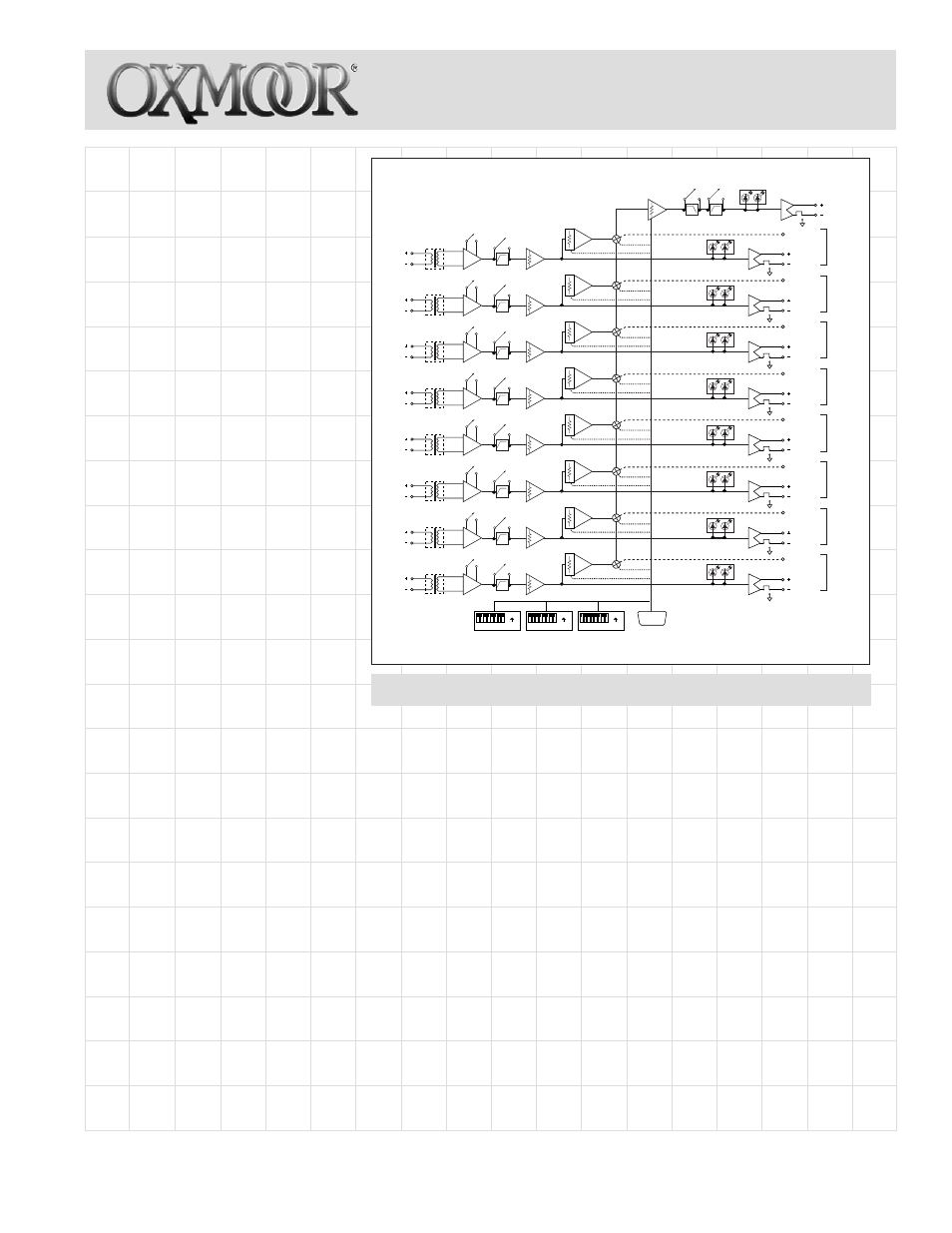
MPM-81 Microphone Preamp/Mixer
••••••••
•••••••
ON
1 2 3 4 5 6 7 8 CH.
ON
1 2 3 4 5 6 7 8 CH.
ON
1 2 3 4 5 6 7 8 CH.
SW 9
SW 10
SW 11
CONTROL PORT
MIC/LINE
VOLUME CONTROL
VCA / LIMITER
VCA / LIMITER
VCA / LIMITER
VCA / LIMITER
VCA / LIMITER
VCA / LIMITER
VCA / LIMITER
VCA / LIMITER
TRANSFORMER
OPTION
CH. 1
CH. 2
CH. 3
CH. 4
CH. 5
CH. 6
CH. 7
CH. 8
DIRECT OUT
MIX OUT
MIX ASSIGN
MIX ASSIGN
MIX ASSIGN
MIX ASSIGN
MIX ASSIGN
MIX ASSIGN
MIX ASSIGN
MIX ASSIGN
DIRECT OUT
DIRECT OUT
DIRECT OUT
DIRECT OUT
DIRECT OUT
DIRECT OUT
DIRECT OUT
TRANSFORMER
OPTION
TRANSFORMER
OPTION
TRANSFORMER
OPTION
TRANSFORMER
OPTION
TRANSFORMER
OPTION
TRANSFORMER
OPTION
TRANSFORMER
OPTION
TRIM CONTROL
TRIM CONTROL
TRIM CONTROL
TRIM CONTROL
TRIM CONTROL
TRIM CONTROL
TRIM CONTROL
TRIM CONTROL
TONE CONTROL BY-PASS
SIGNAL
BAL/UNBALANCE
BAL/UNBALANCE
BAL/UNBALANCE
BAL/UNBALANCE
BAL/UNBALANCE
BAL/UNBALANCE
BAL/UNBALANCE
BAL/UNBALANCE
BAL/UNBALANCE
PEAK
SIGNAL
PEAK
SIGNAL
PEAK
SIGNAL
PEAK
SIGNAL
PEAK
SIGNAL
PEAK
SIGNAL
PEAK
SIGNAL
PEAK
SIGNAL
PEAK
HI PASS
FILTER
HI PASS
FILTER
HI PASS
FILTER
HI PASS
FILTER
HI PASS
FILTER
HI PASS
FILTER
HI PASS
FILTER
HI PASS
FILTER
MIC/LINE
MIC/LINE
MIC/LINE
MIC/LINE
MIC/LINE
MIC/LINE
MIC/LINE
CH. 1
CH. 2
CH. 3
CH. 4
CH. 5
CH. 6
CH. 7
CH. 8