Mcs-mcp master control panel, Combine button, Source button – Oxmoor MCS User Manual
Page 4: Head-table button
SOURCE
HEAD-TABLE
COMBINE
BERKSHIRE ROOM
WYNFREY BALLROOM
SOURCE
HEAD-TABLE
SOURCE
HEAD-TABLE
RIVERCHASE BALLROOM
OFF
ON
COMBINE
COMBINE
MCS-MCP MASTER CONTROL PANEL
Oxmoor’s custom Master Control Panel is
designed to be a user interface to the MCS
System. Thanks to the panel’s highly intuitive
layout, even an unskilled operator can see at a
glance how to operate the MCS system. Its
simplicity results in less time spent in training,
retraining and costly call-backs.
The Master Control Panel presents the user with a
graphic representation of the layout of the rooms
which may be combined. The position of each
switch on this “floor plan” tells the operator
exactly which room or rooms will be affected by
its activation. Each push-button switch includes
an LED TALLY indicator to display its current
status.
There are three types of functions that may be
performed at the Master Control panel:
1. Room combining
2. Source selection
3. Head-table speaker muting
A key switch allows the user to secure all Master
Control Panel functions, preventing unauthorized
personnel from tampering with system settings.
COMBINE Button
The position of each switch on the Master Control
Panel’s room map makes system operation highly
intuitive. To COMBINE two rooms, for example,
the operator simply pushes a button marked
COMBINE that lies at the intersection of the two
rooms. This combines the inputs of the selected
room’s amplifiers and causes all MCS-RP Room
Panels in the combined rooms to be
synchronized.
SOURCE Button
Each room on the Master Control Panel may also
include a SOURCE button. Combining two or
more rooms causes the audio SOURCE in each
room to default to LOCAL (usually a mixer) and
the LOCAL SOURCE to become “active”, or
added to the potential overall mix. Sources may
be deleted or added again with the SOURCE
button. With each push, the SOURCE button
“toggles” between on (source available) and off
(source disconnected). An LED on each button
illuminates to show its status.
The SOURCE function may be used to increase
the number of available inputs or to allow access
to inputs at a variety of locations within the
combined rooms. Unused sources may be
switched off to avoid any chance of accidental
interference.
HEAD-TABLE Button
A HEAD-TABLE switch may be present in each
room on the panel layout. This button provides
the means for switching logic to control external
circuits for muting speakers over a head-table
location in the room indicated. The HEAD-
TABLE switch controls open-collector outputs for
driving relays, provided by others. Each push of
the button toggles the outputs between an on and
off state. An LED on the HEAD-TABLE switch
displays its status.
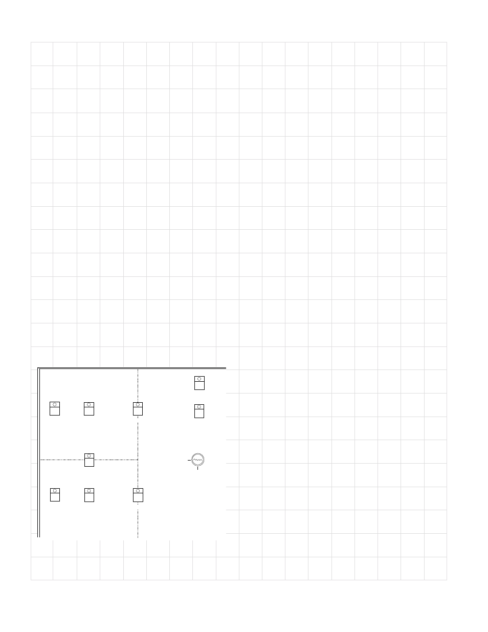
TYPICAL MCS–MCP MASTER CONTROL PANEL SECTION
Page 4