Paxton Superchargers 5.2 Dodge Ram User Manual
Page 18
P/N: 4809625
©2003 Paxton Automotive
All Rights Reserved, Intl. Copr. Secured
25NOV03 v2.0 97-01 5.2/5.9 Dodge(4809625v2.0)
5-2
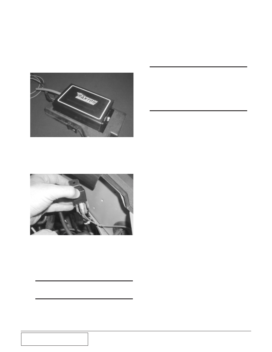
Fig. 5-e
Fig. 5-d
5-3
PAXTON ADDITIONAL INJECTOR
CONTROL INSTALLATION
A.
Remove the fuse box cover located on the
driver’s side near the firewall. Using the
Paxton Injector Controller as a template,
drill two holes and connect the fueler to
the fuse box cover with the supplied hard-
ware. (See Fig. 5-d.)
B.
Attach the Paxton Injector Controller
power wire to the wire from the relay (ter-
minal 87) with a female crimp connector.
(See Fig. 5-e.)
C
Attach the Paxton Injector Controller
ground wire to the wire from the relay
(terminal 85) with a female crimp connec-
tor. Ground the unit to the fuse box
ground terminal.
*** NOTE ***
Refer to Appendix #1017736 for wiring diagram for
AIC Controller and fuel pump.
D.
Using the relay as a template, drill a hole
in the fender well next to the MDS timing
master and mount relay with supplied
screws.
E.
Hook up the vacuum lines as shown in
appendix. (Per schematic.)
*** NOTE ***
Connect the yellow wire with a black tracer to the tach
signal wire. This provides an RPM signal to the AIC
controller. Refer to the factory manual for tach signal
pin location. Since it varies from model year to model
year, it is advised that you look at a shop manual for
your vehicle to locate the correct wire color and pin
location.
G.
Attach the ground wire to the pump.
Route the wires from relay to the AIC.
Route the wires from the relay to the bat-
tery (pos. terminal) inside the fuse box.
Attach the trigger wire from the relay to
the switched 12V source.
H.
Drill a hole in the fender well for a
ground. Scrape and sand the paint off from
around the area to ensure a good connec-
tion. Attach the MSD timing master and
the relay terminal rings to the same
ground.
I.
Route the injector plugs from the fueler
and attach to the injectors.
J.
Attach the wiring harness from the MSD
unit to coil. (Tap into coil wires.) See page
5-3 for the wiring diagram.