Pinnacle Systems UltraTouch UL-101-2P 24VDC User Manual
Models
Models:
UL-101-2P (2 pole, 24VDC)
UL-101-4P (4 pole, 24VDC)
Installation
UltraTouch must be installed in pairs with an anti-tie down
circuit between them to force the user to activate both units
concurrently to initiate hazardous motion. Install units in
such a manner that the wrist or forearm cannot activate
both units while reaching into the point of operation. They
shall be located a minimum of 25” apart, center to center.
Install both units the proper distance away from the point of
operation in accordance with OSHA regulations.
WARNING: Do not over-tighten the four hold down
screws (diagram item #12). Tighten unit on top of gasket
to obtain a snug fit and no more.
WARNING: This unit does not contain anti-tie-down
circuitry. This function is performed either by a UL-601
unit or your own control system. This is an initiation
device only and not a safety device.
Operation
Each UltraTouch contains an optical sensor, capacitive
sensor and circuitry that requires the user to activate both
sensors within a 1/4 sec of each other. When you insert
your hand into the slot, (1) you break the infrared beam,
and (2) your mass is detected by the capacitive sensor (this
dual sensor system prevents accidental activation of the unit
due to shirt sleeves, etc.) The Green LED will light and the
relay(s) will energize.
Pinnacle Systems, Inc.
3715 Swenson Avenue • St. Charles, IL 60174
Customer Service: 630-443-8542 (CST)
(Please have Model, Serial, and Software Revision numbers available)
Sales and Marketing: 800-569-7697 (EST)
www.pinnaclesystems.com
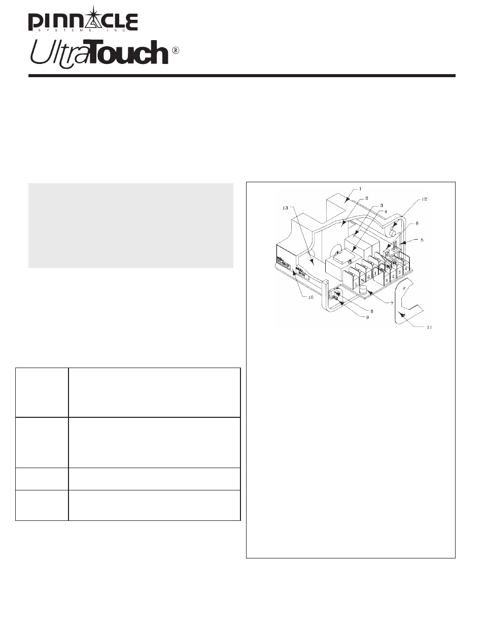
Item
Part No.
Description
1
11-057
IR plastic housing
2
21-024
Brass plate (cap. sensor)
3
32-001
Captive contact relay(s)
7
20-022
1A fuse
8
11-022
Lock down tabs
9
22-008
#4 Phillips flat head screw
10
26-019
Identification label
11
21-008
Gasket
12
22-010
#6-32 x 5/8” Phillips screw
13
52-064
Entire sub-assembly
Terminal Description
L & N
24VDC (polarity protected)
G
Earth Ground (required)
1 & 2
Open when green --|/|--
3 & 4
Closed when green --| | --
Contacts rated at 2 amps @ 120VAC
Second Relay & Terminal Strip:
Repeat of Terminals 1-4 (UL-101-4P)
PN#: 28-012R4
Troubleshooting System
Red light, but no Green light when Hand inserted into
channel:
A) Excessive Sun or incandescent light over top the
UL-101
B) Conductive grease, or liquid in the channel
C) Proximity of channel to nearby metal objects
D) Did not wait 15 seconds at power-up
E) Heavy gloves may require factory adjustment.
Standards:
UL: listed 42EL File SA11766
(UL508 & subject491)
CSA: C22.2 142-M1987
IEC 60947-5-1
Dold Safety output relays UL,CSA,CE certified
IEC ratings:
Ue=24vdc, Ui=600vac, Uimp=600vac
Utilization: (A400) AC15 ,(N250) DC13
IP40 (when mounted with gasket)
1A slo-blow input protection
no output protection
Temp:
Operating: 0°C to 55°C (32°F to 131°F)
Storage: -40°C to 85°C (-40°F to 185°F)
Life:
Mechanical: 50,000,000 cycles
Min Electrical: 200,000 cycles
(replaceable safety relays)