Controls, indicators and connections – TVLogic LQM-171W User Manual
Page 11
Multi F
orma
t L
CD M
onit
or
11
1. SDI IN/OUT
◦
[SDI/CVBS INPUT] HD-SDI. SD-SDI, CVBS Signal input terminal.
◦
LQM-171W detects the input source automatically and displays the source format for SDI and
“NTSC” or “PAL” for CVBS HD-SDI.
◦
[SDI OUTPUT] SDI output terminal.
If the selected input channel is in HD-SDI, the output is in HD-SDI and if the selected input
channel is in SD-SDI input channel, the output is in SD-SDI. However, for analog input channels,
it is A/D converted for SD-SDI output.
2. AUDIO IN/OUT
◦
[AUDIO INPUT] Audio input terminal.
◦
[AUDIO OUTPUT] Audio output terminal for audio input or embedded audio in SDI.
◦
[SPEAKER] Audio output speaker for audio input or embedded audio in SDI.
3. DC IN
◦
DC 12V power input.
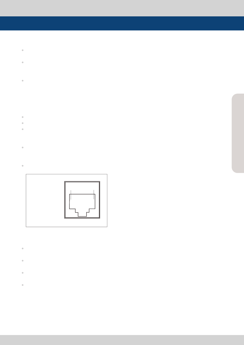
4. REMOTE
◦
Provides connection to monitor control equipment via simple GPI contact closure.
<Remote Connector Pin>
5. COMMUNICATION
◦
[RS232] LQM-171 can communicate through RS232 with other equipment. It is also used for
firmware updates.
◦
[RS422] LQM-171 can communicate through RS422 with other equipment. It is also used for
Dynamic UMD communication.
◦
[Ethernet] LQM-171 can communicate through Ethernet with other equipment. It is also used for
firmware updates.
◦
[USB] LQM-171 can communicate through USB 2.0 with other equipment. It is also used for
firmware updates.
Controls, Indicators and Connections
REMOTE (RJ-45)
1: Pin1
2: Pin2
3: Pin3
4: Pin4
5: Pin5
6: Pin6
7: Pin7
8: GND
1
8