Vectronics HFT-1500 User Manual
Page 11
HFT-1500 Digital Antenna Tuner with Roller Inductor
Owner's Manual
9
METER CALIBRATION
METER CALIBRATION PEOCEDURE
••••
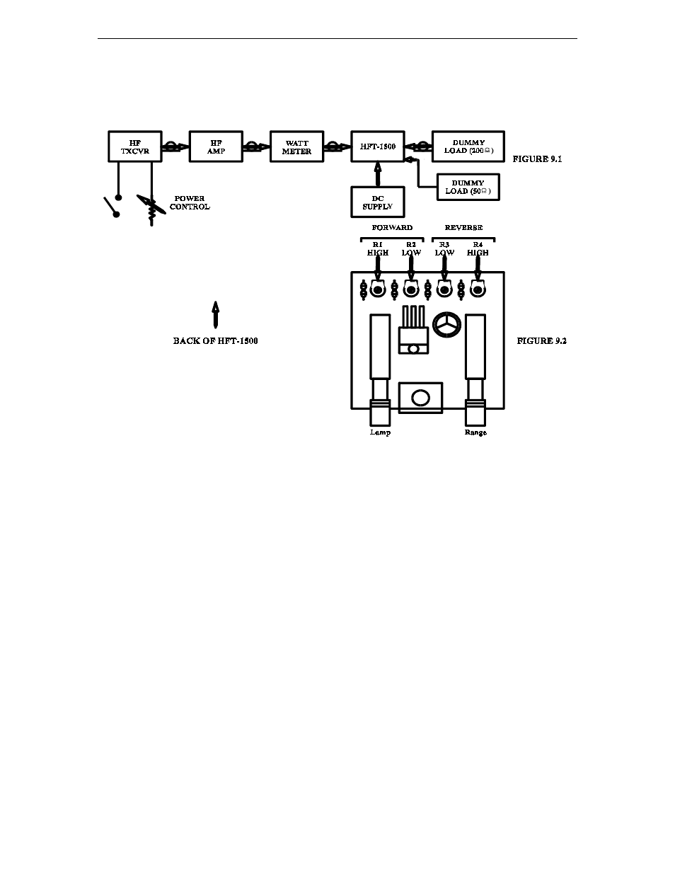
Connect the HFT-1500 as depicted in Figure 9.1.
••••
Connect
external
50
Ω
load to COAX 1 connector and the HF amplifier to the RF
INPUT connector.
••••
Set the COAX 1 DIRECT position on the selector switch.
••••
Set the mid range the two capacitors on the RF sampler board and the four
potentiometers on the switch board.
••••
Select the 300 W range button and zero the two meters using a small slot screwdriver.
••••
Apply 100W of RF at 7.0 MHz from the receiver. By adjusting the trimmer capacitor
closest to the rear panel, null the reflected power needle.
••••
Reverse the connections on RF INPUT and COAX.
••••
Apply 100 watts of RF power at 7.0 MHz. Adjust the trimmer capacitor closest to the
front panel to null the forward power needle.
••••
Depress the RANGE button to select the 3000 Watt range and adjust R4 (in figure
9.2) until the reflected power reads 100 W.
••••
Reduce the power to 10 W, release the RANGE button and adjust R3 until the
reflected power reads 10W.