XTA GQ600 User Manual
Page 13
GQ600 Page 11
Operating Notes
Generally, operating the GQ600 is very straightforward, however certain functions may not be
immediately obvious and these are discussed here.
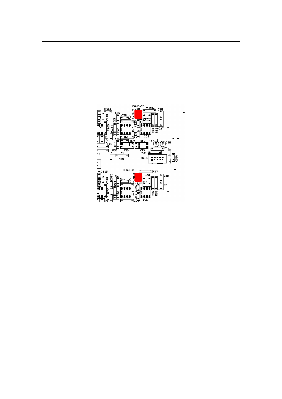
Low Pass Filter. 18dB/octave filters are provided for each channel to provide additional H.F.
driver protection against unwanted high frequency signals. These have negligible effect on
frequency response at 20kHz. All units are factory set with these filters in, if not required these
filters can be removed from the signal path by changing the position of two jumper links on the
main circuit board, see following diagram.
Output Balancing Transformers. Outputs are fully electronically balanced as standard. If
optional output transformers are required proceed as follows:-
1. Remove four "jumpers" from CN4 and CN8 on main circuit board (located near XLR
outputs).
2. Fasten two output transformers type 7470 to the inside of the rear panel chassis, using the
screws and washers provided, through the two mounting holes located above each pair of
input/output XLR’s. Plug in transformer connectors into CN4 and CN8.
3. Monitor output noise of unit and rotate appropriate transformer until noise (hum) is at a
minimum. Fasten transformer in this position and repeat for other channel.
Input Balancing Transformers. Inputs are fully electronically balanced as standard. Input
transformers if required, should be requested at time of purchase if possible. if it necessary to
fit input transformers to existing units proceed as follows:-
On main circuit board.
1. Remove R2, R3, R4, R6, R8, R11, R15, R16, R17, R19, R21, R24.
2. Fit R2 and R15 = 10k ohms, R11 and R24 = 0R0 link.
3. Solder in input transformers type LL1540 to positions TX2 and TX3 on main circuit board.