Aplex Technology ACS-2170 User Manual
Page 31
ACS-2170 User Manual
30
Note:
Before connection, make sure that pinout of the USB Cable is in accordance
with that of the said tables. Any inconformity may cause system down and
even hardware damages.
JP5:
(2.0mm Pitch 2x3 Pin Header), COM3 setting jumper, pin 1~6 are used to
select signal out of pin 9 of COM3 port.
JP5 Pin#
Function
Close 1-2
RI (Ring Indicator) (default)
Close 3-4
COM3 Pin9=+5V (option)
Close 5-6
COM3 Pin9=+12V (option)
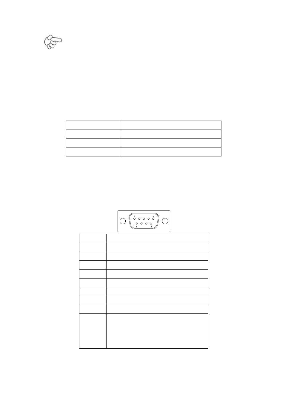
COM3:
(Type DB9), serial port, standard DB9 serial port is provided to make a direct
connection to serial devices. COM3 port is controlled by pins No.1~6 of JP5,
select output Signal RI or 5V or 12v, for details, please refer to description of
JP3.
Pin#
Signal Name
1
DCD# (Data Carrier Detect)
2
RXD (Received Data)
3
TXD (Transmit Data)
4
DTR (Data Terminal Ready)
5
Ground
6
DSR (Data Set Ready)
7
RTS (Request To Send)
8
CTS (Clear To Send)
9
JP5 Setting:
Pin1-2: RI (Ring Indicator) (default)
Pin3-4 : 5V Standby power (option)
Pin5-6: 12V Standby power (option)